Ask Your Question
0

Calculate 3D position from stereo Images

asked 2016-07-26 03:21:55 -0600

benT gravatar image

updated 2016-11-03 07:36:22 -0600

Hi, I have two images taken with a stereo-camera setup (calibrated). I detect markers in both images using the aruco contrib module. How can I calculate the 3D position of the markers edges from the two 2D positions? I found tutorials on how to calculate the depth map, but I do not need the map of the whole image, but just the corners of the markers.

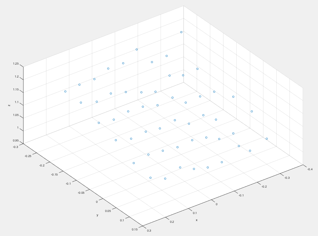
This is a sample plot of the values I get with triangulatePoints on the calibration checkerboard.

image description

edit retag flag offensive close merge delete

Comments

Have you had a look at the reprojectImageTo3D and stereoRectify functions? My understanding was that if you have all the intrinsics and extrinsics of your left and right camera....stereoRectify can produce an output mapping Q that takes the disparity of a pixel and triangulates it.

The documentation says something along the lines that given the rectified co-ordinates <u,v> and the disparity between them as a columnvector of <u,v,disparity, 1="">, you can triangulate them as <x,y,z,w> = Q * columnvector

So if you already have the pixels you want to triangulate and their disparity, you could potentially calculate individual points with the Q matrix. But I stand corrected if someone else knows a little bit more about the functions...see "stereo Odometry- a review of approaches" Peter Protzel

LeGrudge gravatar imageLeGrudge ( 2016-07-27 06:35:40 -0600 )edit

1 answer

Sort by ยป oldest newest most voted
2

answered 2016-07-26 19:33:23 -0600

Tetragramm gravatar image

I believe that triangulatePoints is what you need. I assume you have the projection matrixes for both cameras.

edit flag offensive delete link more

Comments

Seems like exactly what I was looking for, thank you! Documentation seems a bit rare on this one though, but I hope I can get it to work using this answer> http://stackoverflow.com/questions/16... One question remains open> It seems like the points I have to put in are from a distorted image, but mine are already taken from a rectified image. Will this method still work?

benT gravatar imagebenT ( 2016-07-27 01:51:50 -0600 )edit

I've never looked at stereo vision much, but I thought that distortion and rectification were completely different things. Distortion would be individual to one camera lens and is not accounted for in any way with triangulatePoints. Rectification is the relationship between the two cameras, and is the information you need to provide triangulatePoints. At least, that's my understanding.

So if you've corrected for distortion, that's what you want to do.

Tetragramm gravatar imageTetragramm ( 2016-07-27 21:16:28 -0600 )edit

Sorry for closing this so late. I finally got around to test this through and you are absolutely right. I am now calibrating both cameras with calibrateCamera and then I use stereoCalibrate and stereoRectify to get projection matrix for both cameras for triangulatePoints. The featurePoints are the points I get from Aruco. Thanks a lot for your help!

benT gravatar imagebenT ( 2016-10-09 10:15:07 -0600 )edit

@Tetragramm: Do you know how to interpret the results of triangulatePoints? It seems the coordinates are relative to the first camera, but in what units? I can't figure this out. Shouldn't the units be the same as the once used for the square size in the calibration?

benT gravatar imagebenT ( 2016-11-01 05:55:50 -0600 )edit

It should yes, but you need to check your square size was 1x1. So your world points for the squares were (0,0,0), (0,1,0)... ect. If it wasn't, then there's a scale factor to apply.

Tetragramm gravatar imageTetragramm ( 2016-11-01 11:07:42 -0600 )edit

I use 0.07 as square size, since my squares are 0.07m wide. The object points are therefore at (0,0,0), (0,0.07,0)... I thought this was how to get the results scaled correctly, and that the results would be in the same units (m), but they are not.

benT gravatar imagebenT ( 2016-11-02 06:20:39 -0600 )edit

Yes, I would think so. How far off are they? Like, if you hold up the chessboard again, how far apart are the squares?

Try scaling the translation component of the second camera's reprojection matrix by the necessary factor. That could be where the problem is.

Tetragramm gravatar imageTetragramm ( 2016-11-02 18:28:42 -0600 )edit

Hi, thanks a lot for your comment! I did check with the calibration board as you suggested now, and I can see that the average distance between the squares is off by only 5mm at most (square size is 7cm so this is pretty good) and the distance to the camera has an error of about 10%, but the single points are just not very accurate (I never looked at the calibration board before, only at markers, and their position was always off when I objects on them so I thought I misread the values).

I am going to update the question with a sample plot.

I guess my problem was not really with the interpretation of the results, but just the results being bad. Probably the calibration was not as good as I thought. Do you have any tipps on how to do the calibration? How many snapshots should I use?

benT gravatar imagebenT ( 2016-11-03 07:35:06 -0600 )edit

There's no hard a fast rule, but 30-100 pictures. Cover every part of the view, go right up to the edges. Fill the view with the chessboard at least once and also make sure to vary the depth.

Tetragramm gravatar imageTetragramm ( 2016-11-03 10:56:38 -0600 )edit

30-100? Wow. I usually took 20, but with any value higher than that the calibration took forever on my desktop, and I need to do it on my android at the end... Guess I have to be patient! Thanks again for your help

benT gravatar imagebenT ( 2016-11-03 11:04:14 -0600 )edit

Question Tools

1 follower

Stats

Asked: 2016-07-26 03:21:55 -0600

Seen: 5,151 times

Last updated: Nov 03 '16