This forum is disabled, please visit https://forum.opencv.org
| 2020-12-18 08:45:05 -0600 | received badge | ● Famous Question (source) |
| 2019-03-04 08:02:39 -0600 | received badge | ● Notable Question (source) |
| 2018-07-23 15:35:40 -0600 | received badge | ● Popular Question (source) |
| 2016-06-28 10:07:58 -0600 | received badge | ● Enthusiast |
| 2016-06-25 12:32:55 -0600 | commented question | Emgu Camera Calibration with micro video lens So while I am using EmguCV, I am not necessarily sure that this is a problem related to that as opposed to my approach. The way I worded my question, I am more concerned with my procedure and setup as opposed to asking a coding question. Though I can see the confusion based on me linking to an Emgu example. I have now removed that link. |
| 2016-06-25 11:20:09 -0600 | asked a question | Emgu Camera Calibration with micro video lens Hi all, I am using Emgu 2.4.10 in my C# application. I am using the following camera and lens. Camera: https://www.ptgrey.com/flea3-13-mp-mo... Lens: http://www.edmundoptics.com/imaging/i... In this case I also have extra optical elements. The camera goes through a mirror and then a reflection prism that splits the image. Each split image then goes through its own mirror. Essentially this results in two regions: a left region of interest that corresponds to one of the split images, and a right region of interest that corresponds to the other split image. In the end I made the whole resolution of the camera 1264 x 512, and each split image has a resolution of 432 x 512. I performed a separate camera calibration for the left and right region of interest, after the optical elements. I believe theoretically the left and camera calibration should be the same, but there may be slight differences due to alignment issues of the optics and/or camera, which i why I used this approach. However, I seem to be running into a problem. Even after obtaining 25 checkerboard images, I still get a reprojection error of ~1.5 or ~1.6 pixels. Unless I am mistaken, a "good" calibration would have a subpixel reprojection error. I am wondering if this has to do with the fact that I am using a microvideo lens and my physical detection space is small such that the dimension of a grid in the checkerboard pattern is around 1 mm, and this is not allowing me to get a "good" calibration. Or is there another source of my error? Thanks in advance. |
| 2016-04-29 12:05:35 -0600 | commented question | Understanding the camera matrix I tried the python sample with some slight edits for my own images. Interestingly, I got a total error of 0, which seems a bit unbelievable. But I did use this formula: http://opencv-python-tutroals.readthe... By the way, I put an example image in the original post at the end. I had to lower the quality in order to upload it though. |
| 2016-04-29 09:41:09 -0600 | commented question | Understanding the camera matrix I guess it would be good if I could pinpoint whether the error is likely coming from my dataset or in my calculation. Could a "bad" dataset still pass the algorithm, appear to find the corners, and possibly give me the results I am getting? From your experience, when you tried to calculate the focal length in mm as measured from the camera matrix using the dimensional specifications on the camera/lens datasheet, how did it compare to the stated focal length of the lens? Do you have an example? |
| 2016-04-28 12:00:46 -0600 | commented question | Understanding the camera matrix So the key line is: "pattern_points *= square_size" I added that in and started playing with the parameters. I made "square_size" have a value of 1 and then 2. In either case, the camera matrix is the same. The rvecs are also the same. The tvecs however, are twice as great when "square_size" has a value of 2. Still, I don't see why the calculation for focal length doesn't work out, using the data I get from the camera matrix. Is there something I am not taking into account? NOTE: I made an edit to the original post regarding focal length. |
| 2016-04-28 09:59:24 -0600 | commented question | Understanding the camera matrix So that links back to the original C++ sample. Do you mean I have to redefine the python version of "calcChessboardCorners" function? Actually, looking at this example more closely, it looks like there is no adjustment made based on "squareSize" if the chessboard pattern is used as "patternType"? |
| 2016-04-27 16:14:55 -0600 | commented question | Camera Matrix with Extra Optical Elements Because I am using a micro video lens, I had to scale down the chessboard. For comparison, when I printed the original chessboard (https://raw.githubusercontent.com/Its...) I measured a square to be about 21 mm. In comparison, the squaresize for the chessboard I have is about 1.03 mm. Unfortunately, I do not see a way to account for this in python, which I am using: http://docs.opencv.org/2.4/modules/ca.... In contrast, it looks like the C++ version has a variable called "squareSize": https://github.com/Itseez/opencv/blob... . Also, from your own experience, what kind of discrepancy did you see in the two camera matrices? |
| 2016-04-27 15:59:59 -0600 | commented question | Understanding the camera matrix So unless I am mistaken, I do not see a similar "squareSize" variable in the python version: http://docs.opencv.org/2.4/modules/ca... I can see that the routine is finding the corners of the chessboard in the images I have captured. Do I manually need to scale down these values? I printed the original chessboard and each square seems to be about 21 mm. After measuring my chessboard more closely, each square is about 1.03 mm. However, by simply scaling, I do not see how the math could work out. |
| 2016-04-26 10:01:40 -0600 | commented question | Understanding the camera matrix Got it. The grid array refers to the number of inner corners, NOT the number of grids in a row by the number of grids in a column. Other point I wanted to note is that I am dealing with a micro video lens and therefore dealing with smaller field of views / regions of interest. I don't believe this should play a role but just wanted to note that the size of a single grid is about 1.4 mm x 1.4 mm. So if I wanted units of mm, then squareSize = 1.4, correct? |
| 2016-04-26 09:25:38 -0600 | asked a question | Camera Matrix with Extra Optical Elements Hello, I am using a camera sensor with a fixed focal length lens that has a distortion on it. Normally I would use the OpenCV chessboard routine as is to correct for it, but in this case I have extra optical elements. The camera goes through a mirror and then a reflection prism that splits the image. Each split image then goes through its own mirror. Essentially this results in three regions: a left region of interest that corresponds to one of the split images, a right region of interest that corresponds to the other split image, and some dead space in between that I can't detect. My question is how should the camera matrix be obtained?
I don't think the reflection mirrors should be causing too much optical aberration. Thanks in advance. ::::::::::::::::::EDIT:::::::::::::::::So as a point of comparison, I did a test using the first two approaches I mentioned above and here are the resulting intrinsic matrices I obtained from the data. Calibration using only camera without optical elements: mtx = [[ 1.53451091e+03 0.00000000e+00 6.37547946e+02] [ 0.00000000e+00 1.53575661e+03 2.03955413e+02] [ 0.00000000e+00 0.00000000e+00 1.00000000e+00]] dist = [[ -2.90082167e-01 -1.25493796e+00 -6.68277712e-04 5.48729228e-03 3.24470291e+00]] Left region calibration with optical elements: mtx = [[ 1.63242750e+03 0.00000000e+00 7.04154505e+02] [ 0.00000000e+00 1.62893516e+03 2.66533979e+02] [ 0.00000000e+00 0.00000000e+00 1.00000000e+00]] dist = [[ -5.39250573e-01 6.71474407e+00 -7.75939341e-03 3.58186934e-03 -5.96964357e+01] Right region calibration with optical elements: mtx = [[ 1.56749908e+03 0.00000000e+00 3.84091853e+02] [ 0.00000000e+00 1.55558685e+03 1.83966722e+02] [ 0.00000000e+00 0.00000000e+00 1.00000000e+00]] dist = [[ -5.01140894e-01 9.92103465e+00 -1.17531442e-02 -1.02322088e-02 -1.86869431e+02]] So some key points:
|
| 2016-04-26 08:51:58 -0600 | received badge | ● Editor (source) |
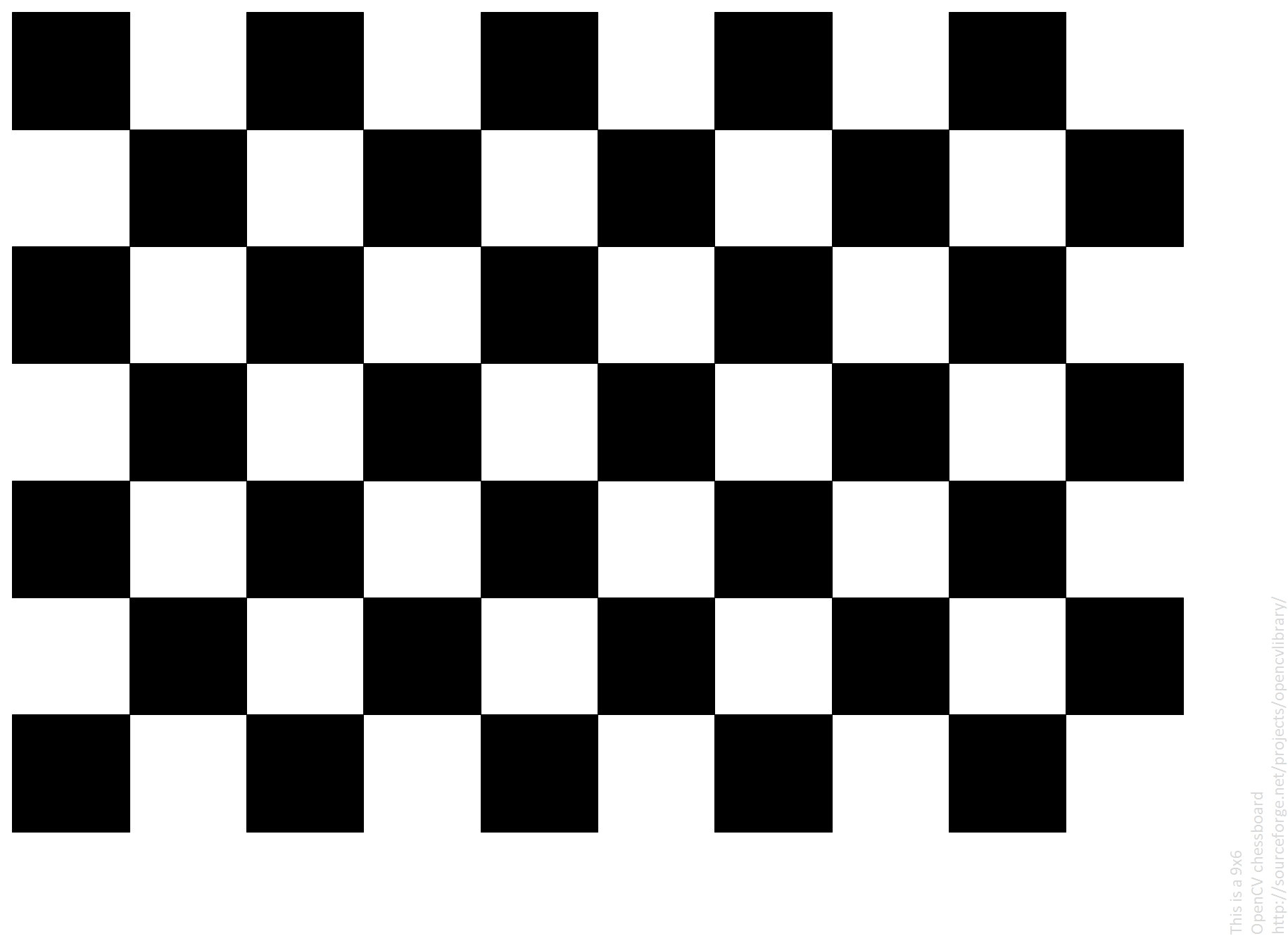
| 2016-04-26 08:46:57 -0600 | commented question | Understanding the camera matrix Hi Eduardo, Thanks for your reply. From my reading, I see that it does ask for the size of the pattern: "Let there be this input chessboard pattern which has a size of 9 X 6." However, as I understand it, this is referring to the number of grids, not the individual size of the grids (in either mm or in). Interestingly enough, to me it appears that their grid example is really 10x7. In your C++ example link: static void calcChessboardCorners(Size boardSize, float squareSize, vector<point3f>& corners, Pattern patternType = CHESSBOARD) I believe you are referring to the input "squareSize", which by default is 1. Is this the value that should be changed, and the input could be in any desired units? I don't believe anything else has to be changed except grid array size? Thanks |
| 2016-03-10 01:28:03 -0600 | asked a question | Understanding the camera matrix Hello all, I used a chessboard calibration procedure to obtain a camera matrix using OpenCV and python based on this tutorial: http://opencv-python-tutroals.readthe... I ran through the sample code on that page and was able to reproduce their results with the chessboard pictures in the OpenCV folder to get a camera matrix. I then tried the same procedure with my own checkerboard grid and camera, and I obtained the following matrix: mtx = [1535 0 638 0 1536 204 0 0 1] I am trying to better understand these results, based on the camera sensor and lens I am using. Based on: http://ksimek.github.io/2013/08/13/in... Fx = fx * W/w Fx = focal length in mm W = sensor width in mm w = image width in pixels fx = focal length in pixels The size of my images: 1264 x 512 (width x height) I am using the following lens: http://www.edmundoptics.com/imaging/i... This has focal length 8 mm. I am using a FL3-U3-13Y3 camera from PtGrey (https://www.ptgrey.com/flea3-13-mp-mo...), which has an image width of 12 mm, according to this picture:
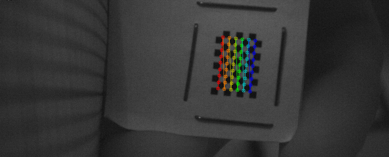
From the camera matrix, fx is the element in the first row, first column. So above, fx = 1535. In short: fx = 1535 pixels (from camera matrix I obtained) w = 1264 pixels (image size I set) W = 12 mm (from datasheet) Fx = 8 mm (from datasheet) Using: Fx = fx * W/w, we would expect Fx = 1535 * 12 / 1264 = 14.57 mm But the actual lens is 8 mm. Why the discrepancy? I would think that the actual size of a chess grid would have to be known, but I did not see mention of manipulation of that in the tutorial link I provided. I basically had to scale down the chessboard grid so that it would work with my camera setup. I would appreciate any help or insight on this. Thanks in advance EDIT:Actually to be more specific, the lens has a maximum camera sensor format of 1/3", while the camera sensor format is 1/2". I found an article on this: http://www.cambridgeincolour.com/tuto... Focal length multiplier = (1/2) / (1/3) = 1.5 Focal length of lens as listed on datasheet = 8 mm Equivalent focal length of lens= 1.5 * 8 mm = 12 mm Still, 12 mm is off from 14.57 mm. Am I not factoring something else in my calculation? Could this be happening from bad images that still happen to find the chessboard corners? Below is an example image:
|