Ask Your Question
3

Can i get 2d world coordinates from a single image ([u,v] coords)?

asked 2015-07-24 13:20:56 -0600

mmo gravatar image

I'm new to everything vision!

I've read some similar posts but I can't get my head around it. Here's what I'm trying to do:

-I have a single camera looking down on a surface (we can assume it's normal to the surface) and I want to detect a hole and obtain it's [X,Y] from a world coordinate I have determined. -I do not care about the -Z info, I know the real hole diameter.

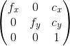
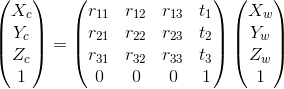
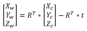
I have calibrated my camera and have the intrinsic matrix. For the extrinsic info I have taken 4 points from my image(mouse callback) and their correspondent 4-real points from the world coordinate to use 'solvePnP' and 'Rodrigues'(for the rotation matrix).

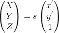
I can detect the hole using HoughCircles and I have the center in [u,v] coords.

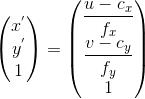
Now, is there a way to obtain that [u,v] point in [X,Y] in my defined coordinate system???
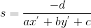
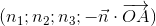
edit retag flag offensive close merge delete

3 answers

Sort by » oldest newest most voted
10

answered 2015-07-25 18:10:32 -0600

Eduardo gravatar image

updated 2016-11-27 18:06:20 -0600

It should be possible if you know:

  • the camera intrinsic parameters: camera intrinsic parameters
  • the camera pose: camera pose
  • the plane equation that contains the hole: plane equation

For the plane equation, you should find a way to know the coordinates of 3 points in the world coordinate that lie on the same plane that contains the hole.

Then, you can change their coordinates to the camera frame knowing the camera pose and compute the plane equation.

Steps

Convert the 2D image coordinate of the hole in the normalized camera frame: image description

Get the scale factor: image description

The 3D coordinate of the hole in the camera frame is then: image description


Plane Equation

Different formulas:

  • plane equation
  • plane equation
  • plane equation
  • plane equation

You can then identify the quadruplet image description with the quadruplet image description.

We can have a first plane that contains the hole and another plane parallel to the first but which passes by a point at a normalized coordinate z=1 (obtained from the 2d coordinate): image description.

For the two plane equations, the coefficients a, b, c are the same, only the coefficient d is different.

The "scale factor" is then: image description

Edit: Your case is a little easier as the camera is almost parallel to the surface. You could use the hole diameter to compute the "scale factor" knowing the ratio between the hole diameter in the real world and the hole diameter in pixel after a calibration step.


Edit2 (2016/11/27):

Here a full working example. The data used to estimate the camera intrinsic matrix can be found in the OpenCV sample data directory (I used the left images). Should also be possible to do the same by computing the point from the intersection between the image ray and the plane.

The example code is a little bit long. What it does:

  • extract 2D image corners using cv::findChessboardCorners (image used is left04.jpg)
  • compute the camera pose using cv::solvePnP
  • check the camera pose by computing the RMS reprojection error
  • compute the plane equation from 3 points
  • compute the 3D point in camera and object frame using the 2D image coordinate, the plane equation and the camera pose and compute the RMS error
  • note: here the distorsion coefficients are not taken into account when computing the normalized camera coordinates

Code:

#include <iostream>
#include <opencv2/opencv.hpp>


//@ref: http://answers.opencv.org/question/67008/can-i-get-2d-world-coordinates-from-a-single-image-uv-coords/

enum Pattern { CHESSBOARD, CIRCLES_GRID, ASYMMETRIC_CIRCLES_GRID };

static void calcChessboardCorners(cv::Size boardSize, float squareSize, std::vector<cv::Point3f>& corners, Pattern patternType = CHESSBOARD) {
  corners.resize(0);

  switch(patternType) {
    case CHESSBOARD:
    case CIRCLES_GRID:
      for( int i = 0; i < boardSize.height; i++ )
        for( int j = 0; j < boardSize.width; j++ )
          corners.push_back(cv::Point3f(float(j*squareSize),
                                    float(i*squareSize), 0));
      break;

    case ASYMMETRIC_CIRCLES_GRID:
      for( int i = 0; i < boardSize.height; i++ )
        for( int j = 0; j < boardSize.width; j++ )
          corners.push_back(cv::Point3f(float((2*j + i % 2)*squareSize),
                                    float(i*squareSize), 0));
      break;

    default:
      CV_Error(cv::Error::StsBadArg, "Unknown pattern type\n");
  }
}

double checkCameraPose(const std::vector<cv::Point3f> &modelPts, const std::vector<cv::Point2f> &imagePts, const cv::Mat &cameraMatrix,
                       const cv::Mat &distCoeffs, const ...
(more)
edit flag offensive delete link more

Comments

This is valid whether the camera is normal to the plane or not, right?

Pedro Batista gravatar imagePedro Batista ( 2016-11-22 04:40:13 -0600 )edit

Yes, it should work in both cases.

Eduardo gravatar imageEduardo ( 2016-11-22 07:51:51 -0600 )edit

How can I obtain the camera pose (rotation and translation) in relation to my plane? And the intrinsic parameters, can I obtain them using the camera calibration sample?

Pedro Batista gravatar imagePedro Batista ( 2016-11-22 11:04:50 -0600 )edit

For the camera pose, the easiest solution should be to use a marker tag (or multiples tags), or any solution where you can use cv::solvePnP.

Yes, the intrinsic parameters are the one from the calibration sample (note that I don't take into account the distorsion, it should be ok for camera with low distorsion).

Eduardo gravatar imageEduardo ( 2016-11-22 12:28:52 -0600 )edit

I have a camera looking at a plane with 4 defined corners (I know the image coordinates of these corners). I also know the camera intrinsic parameters and distortion coeffs.

I can detect flat objects on this plane, but now I'd like to know its coordinates in the plane's coordinate system: This coordinate system starts at [0,0] in one of the corners, and ends at [1,1] at the opposite corner.

So, if I understood your answer correctly, first thing I need to know is the Translation and Rotation vecs, which can be obtained by using the cv::solvePnP function. I assume that I can use the four known corners and use my [0,0] - [1,1] system as objectPoitns, and in the image points I input the corresponding known image coordinates. After this I should have everything I need to to get object coords.

Pedro Batista gravatar imagePedro Batista ( 2016-11-23 05:22:22 -0600 )edit

Is my reasoning correct?

Pedro Batista gravatar imagePedro Batista ( 2016-11-23 05:23:27 -0600 )edit

Yes, I think that with this method you should be able to get what you want:

  • the rotation and translation vectors should be up to a scale but it doesn't matter in your case if you are not interested in the true 3D coordinate
  • from a 2D image coordinate, you will get the 3D in your object coordinate, in the same scale than [0,0] - [1,1].
  • if you are successful, I am interested by an update
Eduardo gravatar imageEduardo ( 2016-11-23 08:55:11 -0600 )edit

Do you know if the rotation and translation already have into account the distortion coeffs (Since I needed them for solvePnP)? I'm not sure how I should take the distortion into account when transforming image coordinates to plane coordinates.

Pedro Batista gravatar imagePedro Batista ( 2016-11-23 09:11:29 -0600 )edit

cv::solvePnP takes the distorsion coefficients. Another solution is to undistort the image and pass a zero-distorsion coefficient vector.

Eduardo gravatar imageEduardo ( 2016-11-23 10:12:34 -0600 )edit

For some reason I really couldn't find a model to transform the coordinates. But your cv::projectPoints() verification gave me an idea. Since my calibrated surface is always the same, and number of possible object locations is finite (its limited to the number of pixels in the calibrated area), I just need to project ALL possible real coordinates in that area and use it to define a LuT to be consulted in real-time.

I did not give up yet in finding the model, I will keep trying to do it but for now this solution is working according to my needs (seems pretty accurate).

Pedro Batista gravatar imagePedro Batista ( 2016-11-28 11:02:57 -0600 )edit
4

answered 2015-08-18 10:36:21 -0600

mmo gravatar image

Thanks for the answer! Very helpuful. Sorry I took a long time to post how I solved my problem. I ended up using some of your equations and an additional one.

  • From the camera intrinsic parameters I obtained: fx, fy, cx, and cy.
  • From previous measurements I have the [object points] and their correspondent [image points] (used in solvePnP). I obtained the [image points] with 'mouse callback' function.
  • 'Rodrigues' function gets me the Rotation Matrix with the 'rvec' from 'solvePnP'.
  • 'HoughCircles' gives me the [u,v] of the hole center I'm identifying.
  • Converted the 2D image coordinate of the hole in the normalized camera frame. [x', y', 1] (above equation)
  • I made the scale factor 's' the distance from the surface to the camera sensor.
  • Multiply 's' by the normalize camera sensor. (equation above).
  • Finally, I use this equation to transfom the 3D coordinate in camera frame to my world frame.

'R^T' is the transposed rotation matrix and 't' is tvec.

image description

Results where pretty accurate. I've changed some things since then and I don't remember the correct tolerance but it was better than I expected. I think a different lens might help to, mine has a fish eye distortion and even the 'undistort' function doesn't fix it completely. The edges are no good.

Thanks again.

edit flag offensive delete link more
0

answered 2016-11-23 11:53:29 -0600

Couldn't write this up in a comment, so I'll make it an answer instead even though this is a question.

I calibrated my camera and obtain the cameraMatrix and distortion coefficients. I believe they are correct because if I undistort my image it will look good.

I'm attempting to transform image coordinates to plane coordinates in the following setup:

image description

Each black square is one corner of my calibrated surface. I know the image coordinates of each of these squares, in my current calibration they are:

TopLeft: [170, 243]
TopRight: [402, 238]
BottomLeft: [82, 383]
BottomRight: [513, 346]

So, now I want a new coordinate system, so that

TopLeft: [0, 0]
TopRight: [0, 1]
BottomLeft: [1, 0]
BottomRight: [1, 1]

So, now I want to detect objects inside this area, and transform their images coordinates to my [0,0] - [1,1] system.

I used these four corners as input for the cv::solvePnP function and then used cv::rodrigues to obtain the rotation matrix. In this current calibration, these are my results:

translation vec: 
[-0.6335161884885361;
 0.0327718985712979;
 2.090753021694066]

Rotation Mat: 
[0.994295199236491, 0.1037446225804736, 0.02478124413546758;
 -0.05350435092326501, 0.2841225297901329, 0.9572939321326209;
 0.09227318791256028, -0.9531586653602274, 0.2880524560582033]

So, I would think that this would be enough for me to transform any image point inside that area and turn it into [0; 1] coordinates. To test, I tried to make the calculations for the image points that I already know (the corners).

If I try to use these matrices to transform the TopLeft corner [170, 243], I should be able to get [0, 0] result. But this is not what I am getting, so obviously I am missing something along the process, since I know that this task is possible to achieve.

edit flag offensive delete link more

Comments

The rotation matrix doesn't look too good... those 0.99 values do not seem right. If I use I take an image coordinate and run it through that matrix it doesn't look like it would turn into a 0;1 coordinate

Pedro Batista gravatar imagePedro Batista ( 2016-11-23 12:00:58 -0600 )edit

So, you are saying that if you do: [u, v, 1]^T = K . (R | t) . [0, 0, 0, 1]^T is not equal to [170, 243, 1]?

If so, the ouput of cv::solvePnP is not correct. Instead, you could try to use the chessboard image (more points).

Eduardo gravatar imageEduardo ( 2016-11-24 03:33:34 -0600 )edit

Ok, I will try to add more known points to the SolvePNP function and try again.

Pedro Batista gravatar imagePedro Batista ( 2016-11-24 05:16:23 -0600 )edit

While doing test calculations using the formula in your comment, I would input plane coordinates for known image points. I realized that the resulting vector never had the z value = 1. It is always something like [400, 500, 1,7].

It felt like normalizing this result by dividing the vector by the z Value would be correct, and it turns out that the output started to make sense. I calculated image coordinates for known points, and it the maximum error I am getting is around 20 pixels (error grows with distance to the camera). My application needs good accuracy, but I may be able to do some post-processing on these results to fix the resulting position.

Pedro Batista gravatar imagePedro Batista ( 2016-11-24 08:27:02 -0600 )edit

Also, I tested error for transformation matrix calculated with 4 points and 13 points, and the accuracy does not improve that much by adding more points.

Pedro Batista gravatar imagePedro Batista ( 2016-11-24 08:29:35 -0600 )edit

Maybe a stupid question: your pattern is perfectly square (to be able to get [0,0] [1,1] coordinates)?

Also, I would validate the process with a chessboard pattern just to be sure.

Eduardo gravatar imageEduardo ( 2016-11-24 08:53:46 -0600 )edit

No, it is not perfectly square, it is just a manually made square.

I used the chessboard to get the intrinsics. You are telling me to lay the chessboard on the surface and let the calibrator calculate the rvec and tvec?

Pedro Batista gravatar imagePedro Batista ( 2016-11-24 09:29:13 -0600 )edit

I was thinking about using the chessboard to:

  • be sure that the pose returned by cv::solvePnP is quite accurate bytesting if the projection of the object points using the pose and the intrinsic is ok or not (compared to the chessboard image corners)
  • validate the principle using the corners detected by cv::findChessboardCorners and check the accuracy with the true model points

If all these steps are validated, you should be able to determine where is the issue when you switch to your custom case (problem with the pose for instance, accuracy of the corners detected, limitation of the method, etc.).

Eduardo gravatar imageEduardo ( 2016-11-24 09:36:40 -0600 )edit

Can you help me inverting the [u, v, 1]^T = K . (R | t) . [X, Y, Z, 1]^T to solve for [X,Y,Z]? The problem is that (R|t) is not invertible so I'm not sure how to proceed, and algebra class was way to long ago :P

Pedro Batista gravatar imagePedro Batista ( 2016-11-25 09:15:12 -0600 )edit

I tried to transform this matrix system to a normal system of equations. That is equivalent to:

u = aX + bY + bZ + d; v = eX + fY + gZ + h; w = ix + jy + k*z + l. in which a,b,c,d... are the components of result of the dotProduct K.(R | t): a = fx * r11 + cx * r31 and so on.

w should always be 1, but for some reason I need to divide u and v by w so that I obtain correct imgPoints (maybe the problem is this?).

I tested this and get same results as matrix operations.

Then, I used a website to solve that system for X,Y,Z and I get this .

Pedro Batista gravatar imagePedro Batista ( 2016-11-25 09:43:45 -0600 )edit

Question Tools

2 followers

Stats

Asked: 2015-07-24 13:20:56 -0600

Seen: 12,381 times

Last updated: Nov 27 '16