Ask Your Question
0

Isn't the calcOpticalFlowFarneback example calculating hue wrong?

asked 2019-02-09 23:14:30 -0600

kebwi gravatar image

updated 2019-02-10 13:30:04 -0600

I believe the canonical optical flow example is the one provided at https://docs.opencv.org/master/d7/d8b/tutorial_py_lucas_kanade.html. It takes a flow angle, converted from Cartesian to polar, in the range (0, 2Pi) and converts it to hue by ang*180/np.pi/2, producing hue in the range (0, 180). This doesn't make any sense to me. I think hue, as a polar entity itself, should fully encompass the direction of the flow, hence it should have the range (0, 360), which is simply achieved by ang*180/np.pi.

I am very perplexed by this since the seemingly correct equation is actually the simpler option. Someone actually added an extra division by two, thereby breaking the equation (by my reasoning). Consequently, I am concerned I am misunderstanding this somehow. But if you run the optical flow algorithm on artificially generated data (painted rectangles offset in the four cardinal directions), you get much more sensible results using my recommended equation. Hue encompasses and utilizes the entire hue range and depicts smooth direction gradients. The existing example only utilizes half the available hue (from red to cyan), and worse than discarding half the hue availability, it also yields a discontinuity between directions 359 and 0, depicted as a sudden jump from cyan to red. This really doesn't make any sense.

How has this example stood for so long in this form? Further compounding my confusion, this apparent error has propagated to other projects, as shown at https://www.programcreek.com/python/example/89313/cv2.calcOpticalFlowFarneback. Consequently, as I stated above, I genuinely feel I am making some sort of mistake on all of this. I can't be the first person to have ever noticed this, so I must be interpreting it incorrectly, right? I'm very confused.

What does everyone else think about this?

Thanks.

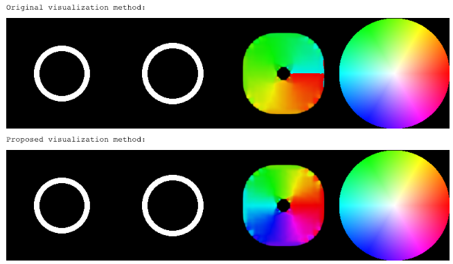
Here is an example of the old method of flow-direction/hue mapping and my proposed method. The optical flow consists of a radially expanding ring, so as to show flow in all possible directions and their associated color mapping. I have included a typical HSV color wheel for comparison. I won't bother pasting all the code in here. I'll add it as an answer tomorrow (I can't answer it today because my account is too young).

image description

edit retag flag offensive close merge delete

Comments

maybe it helps, if you know, that hue is in [0..180], not in [0..360] in opencv (since it has to fit into a byte)

berak gravatar imageberak ( 2019-02-10 02:20:23 -0600 )edit

Oookay, but the example is still wrong. I guess it could explain how someone might create the example incorrectly to begin with, but it's still easy to get around this one-byte discrepancy to create a properly working angle-hue encoding. So the example should probably be updated.

kebwi gravatar imagekebwi ( 2019-02-10 02:27:38 -0600 )edit

if you WANT the hue in [0..360], convert the image to float before the hsv conversion.

and again, it's just some attempt at visualizing something, don't take it too serious ....

berak gravatar imageberak ( 2019-02-10 02:33:16 -0600 )edit

I'm honestly surprised at your response. The example reveals discontinuous hue transitions from cyan to red to indicate an epsilon change in optical flow direction, while also not honoring the intuitive mapping between hue and direction shown on an HSV color wheel. I spent a bit of time figuring out how this was occurring, and your response is "go ahead and fix it so it works properly if you want, but don't 'take it too seriously' that the documented example of how to use this function is basically broken because attempting to 'visualize something' isn't very important anyway."

So, in other words, the example won't be fixed and therefore someone else will likely needlessly puzzle over this conundrum in the future.

I was just trying to help. I'm sorry if I intruded. Good luck.

kebwi gravatar imagekebwi ( 2019-02-10 02:51:52 -0600 )edit

in other words, the example won't be fixed

oh , if you can please go ahead and do so !

while also not honoring the intuitive mapping between hue and direction shown on an HSV color wheel

yea, that would be actually a good idea.

berak gravatar imageberak ( 2019-02-10 02:58:38 -0600 )edit
1

Fair enough, but I admit to having no history of contribution to OpenCV. I'll see if I can get in there and submit the change myself. Cheers!

kebwi gravatar imagekebwi ( 2019-02-10 03:01:19 -0600 )edit

@kebwi Are you talking about Dense Optical Flow in OpenCV example ?If yes I don't understand your problem. HSV space is only use for display : result is an image with false color. You can use full scale for H but is result displayed visualy better?

LBerger gravatar imageLBerger ( 2019-02-10 03:20:53 -0600 )edit

I have described two ways in which the visualization would be better. Utilizing the full hue range doubles the useful colors available for discerning flow direction. More critically, the proposed method does not introduce color discontinuities at minute differences in flow direction between 359 and 0 degrees (whereas the existing method jumps from cyan to red). See my example in the answers section below.

Oh, since I'm a new user, it won't let me answer my own question. I guess I'll paste the answer in tomorrow. Sheesh. I can't believe this.

kebwi gravatar imagekebwi ( 2019-02-10 12:55:13 -0600 )edit

In lieu of waiting until tomorrow to post an answer, I added it as an edit to the original question. Please see above for further clarification.

kebwi gravatar imagekebwi ( 2019-02-10 13:30:57 -0600 )edit

2 answers

Sort by ยป oldest newest most voted
1

answered 2019-02-12 20:26:40 -0600

kebwi gravatar image

Here's the code I used to generate the image that I added to the original question. I modified it just a little bit to map radius to value instead of saturation to be in closer correspondence with the optical flow output. Admittedly, HSV wheels generally assign radius to saturation. My goal here is to provide the clearest possible data visualization of optical flow. Of course, most of the responses to my question seem to indicate that no one else considers this to be very important, so whatever. Just trying to help.

from PIL import Image, ImageDraw
import numpy as np
import cv2

wh = 200
wh_2 = wh / 2

# Generate a standard HSV color wheel
hsv_color_wheel = np.zeros((wh, wh, 3))
for y in range(wh):
    yy = y - wh_2
    for x in range(wh):
        xx = x - wh_2
        radius = math.sqrt(xx**2 + yy**2)
        if radius < wh_2:
            angle = math.atan2(xx, yy)
            angle = 360 - (angle * 180 / np.pi)
#             hsv_color_wheel[x, y] = (angle, radius / wh_2, 255) # Radius as saturation, which is a more conventional HSV wheel
            hsv_color_wheel[x, y] = (angle, 1, radius / wh_2 * 255) # Radius as value, which maps optical flow's magnitude

hsv_color_wheel = np.asarray(hsv_color_wheel, dtype=np.float32)
hsv_color_wheel = cv2.cvtColor(hsv_color_wheel, cv2.COLOR_HSV2RGB)

hsv_color_wheel_flat = hsv_color_wheel.reshape(wh * wh, 3)
hsv_color_wheel_flat_tuple = [tuple(v) for v in hsv_color_wheel_flat]

hsv_color_wheel_img = Image.new("RGB", (wh, wh))
hsv_color_wheel_img.putdata(hsv_color_wheel_flat_tuple)

# Generate some shifted boxes to demonstrate optical flow
box_sz = wh / 5
box_sz_2 = 2 * wh / 5
box_sz_3 = 3 * wh / 5
dim = (wh, wh)
img1 = Image.new("L", dim)
img2 = Image.new("L", dim)

shift = 5
draw = ImageDraw.Draw(img1)
draw.ellipse((wh/5+10, wh/5+10, 4*wh/5-10, 4*wh/5-10), 255)
draw.ellipse((wh/5+20, wh/5+20, 4*wh/5-20, 4*wh/5-20), 0)
draw = ImageDraw.Draw(img2)
draw.ellipse((wh/5+10 - shift, wh/5+10 - shift, 4*wh/5-10 + shift, 4*wh/5-10 + shift), 255)
draw.ellipse((wh/5+20 - shift, wh/5+20 - shift, 4*wh/5-20 + shift, 4*wh/5-20 + shift), 0)

img1_arr = np.array(img1)
img2_arr = np.array(img2)

# Run optical flow and visualize two possible ways
for method in [1, 2]:
    flow = cv2.calcOpticalFlowFarneback(img1_arr, img2_arr, None, 0.5, 3, 40, 3, 5, 1.2, 0)

    # Convert from cartesian to polar
    mag, ang = cv2.cartToPolar(flow[..., 0], flow[..., 1])

    # Create an HSV image
    hsv = np.zeros((img1.size[0], img1.size[1], 3))
    hsv[:,:,1] = 1  # Full saturation
    # Set hue from the flow direction
    if method == 1:
        hsv[:,:,0] = ang * (180 / np.pi / 2)
    else:
        hsv[:,:,0] = 360 - (ang * (180 / np.pi))
    # Set value from the flow magnitude
    hsv[:,:,2] = cv2.normalize(mag, None, 0, 255, cv2.NORM_MINMAX)
    # Convert HSV to int32's
    hsv = np.asarray(hsv, dtype=np.float32)
    rgb_flow = cv2.cvtColor(hsv,cv2.COLOR_HSV2RGB)

    # Convert to an image
    rgb_flow_flat = rgb_flow.reshape(rgb_flow.shape[0] * rgb_flow.shape[1], 3)
    rgb_flow_flat_tuple = [tuple(v) for v in rgb_flow_flat]
    flow_img = Image.new("RGB", img1.size)
    flow_img.putdata(rgb_flow_flat_tuple)

    analysis_img = Image.new("RGB", (img1.size[0 ...
(more)
edit flag offensive delete link more
0

answered 2019-02-10 09:45:40 -0600

supra56 gravatar image

updated 2019-02-10 09:46:59 -0600

This code will work merely OpenCV3.x. But I haven't tested on OpenCV4.0.1. Btw, it is essential to used cv2.remap. Code:

def interpolate_frames(frame, coords, flow, n_frames):
    frames = [frame]
    for f in range(1, n_frames):
        pixel_map = coords + (f/n_frames) * flow
        inter_frame = cv2.remap(frame, pixel_map, None, cv2.INTER_LINEAR)
        frames.append(inter_frame)
    return frames

flow = cv2.calcOpticalFlowFarneback(curr, prev, None, *optflow_params)
inter_frames = interpolate_frames(prev_frame, coords, flow, 4)
edit flag offensive delete link more

Comments

Forgotten. I am using raspberry pi 3b/+ using picamera.

supra56 gravatar imagesupra56 ( 2019-02-10 09:48:25 -0600 )edit

Question Tools

1 follower

Stats

Asked: 2019-02-09 23:14:30 -0600

Seen: 1,416 times

Last updated: Feb 12 '19