Ask Your Question
0

Turning ArUco marker in parallel with camera plane

asked 2017-03-30 04:19:28 -0600

tischenkoalex gravatar image

updated 2017-04-17 19:23:44 -0600

Eduardo gravatar image

I need to warp the image to fix its perspective distortion based on detected marker. In other words - to get the plane where the marker lays become parallel to the camera plane.

In general it works for me, when I simply map points of perspective-distorted marker to its orthogonal position (Sketch) with getPerspectiveTranfrorm() and then warpPerspective(), which warps whole image:

The following are sample params for getPerspectiveTransform()

src1 (100, 100) => dst1 (100, 100)
src2 (110, 190) => dst2 (100, 200)
src3: (190, 190) => dst3 (200, 200)
src4: (200, 100) => dst4 (200, 100)

The result looks OK, but not always, so I think that this way is wrong.

My assumption that since for detected marker I can get its pose estimation (which shows its relation to camera) I can calculate required marker position (or camera position?) using marker points and rotation/translation vectors.

Now I'm stuck basically not understanding the math solution. Could you advise?

UPDATE

The following is a source image with detected markers. The white circles represent the desired position of marker that will be used in getPerspectiveTransform(). source
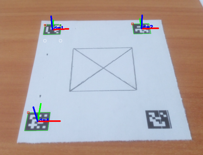
Source corners: [479, 335; 530, 333; 528, 363; 475, 365]
Result corners: [479, 335; 529, 335; 529, 385; 479, 385]

The following is the result image, which is still distorted:
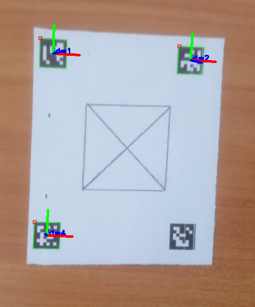
image description

edit retag flag offensive close merge delete

Comments

Maybe you can add a sample data: image + extracted corners points in text?

As the marker is planar, the transformation should be a homography. Knowing the two camera poses (current pose estimated and desired camera pose), you should be able to compute the homography matrix from the camera displacement. Once you have the homography, you will have to use warpPerspective(). You can also compare the two homography matrices.

Eduardo gravatar imageEduardo ( 2017-03-30 13:10:59 -0600 )edit

I added source images and corner coordinates. Will read more on homography. Thanks!

tischenkoalex gravatar imagetischenkoalex ( 2017-03-31 07:20:58 -0600 )edit

I would use rather one or multiple corners but for all the markers to estimate the perspective transformation (you will have to change also the desired coordinates).

Looks like your extracted corner coordinates are integer numbers. Maybe you could check also if you can refine the coordinates of the corners (subpixel accuray, see here in Corner Refinement section) and use cv::Point2f or cv::Point2d.

Eduardo gravatar imageEduardo ( 2017-03-31 10:14:28 -0600 )edit

Yes, I plan to switch to subpixel accuracy too. Just wanted first to make sure that I'm not going in wrong direction by not calculating desired coordinates from vectors. I didn't check the homography topic yet though... I believe it will give me more understanding.

tischenkoalex gravatar imagetischenkoalex ( 2017-03-31 10:28:43 -0600 )edit

I think the issue you have should come from some noise, incertitude in the corner coordinates that will affect the estimation of the perspective transformation. Using points more spread out should lead to better results in my opinion. The original image can also be distorted due to the camera lens and can have an impact somehow.

Note: I think that findHomography() or perspectiveTransform() should give you the same transformation matrix, you have to check.

Eduardo gravatar imageEduardo ( 2017-03-31 11:58:18 -0600 )edit

I switched to use ARUCO Board and it improved accuracy a lot. findHomography() and getPerspectiveTransform() provide the following result for me.

tischenkoalex gravatar imagetischenkoalex ( 2017-04-04 03:33:05 -0600 )edit

1 answer

Sort by ยป oldest newest most voted
1

answered 2017-04-17 19:22:04 -0600

Eduardo gravatar image

updated 2017-04-17 19:58:36 -0600

I have written in this answer some experimentations I did to understand more the concept of homography. Even if this is not really an answer of the original post, I hope it could also be useful to other people and it is a good way for me to summarize all the information I gathered. I have also added the necessary code to check and make the link between the theory and the practice.


What is the homography matrix?

For the theory, just refer to a computer vision course (e.g. Lecture 16: Planar Homographies, ...) or book (e.g. Multiple View Geometry in Computer Vision, Computer Vision: Algorithms and Applications, ...). Quickly, the planar homography relates the transformation between two planes (up to a scale): Homography

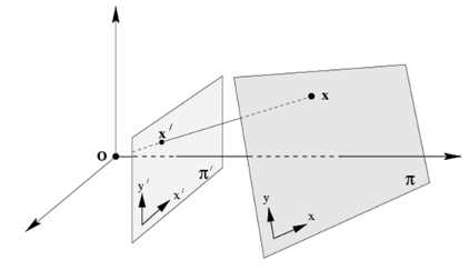
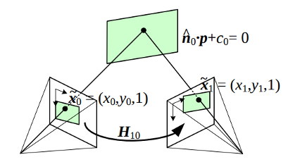
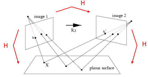
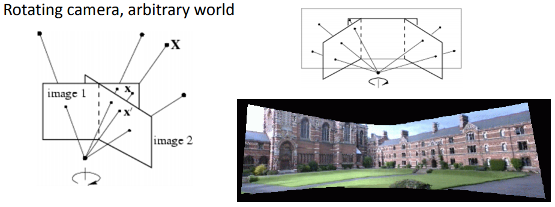
This planar transformation can be between:

  • a planar object and the image plane (image from here, p9):

Homography transformation

  • a planar surface viewed by two cameras (image from here, p56 and here, p10):

Homography transformation2-1 Homography transformation2-2

  • a rotating camera around its axis of projection, equivalent to consider that the points are on a plane at infinity (image from here, p11):

Homography transformation3


How the homography can be useful?

  • Camera pose estimation with coplanar points (see here or here, p30), the homography matrix can be estimated using the DLT (Direct Linear Transform) algorithm
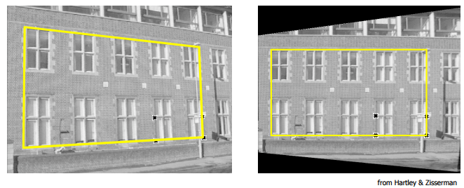
  • Perspective removal, correction: Perspective correction
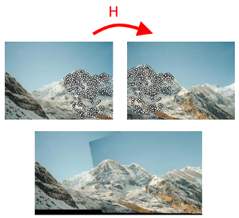
  • Panorama stitching: Panorama stitching

Demo 1: perspective correction

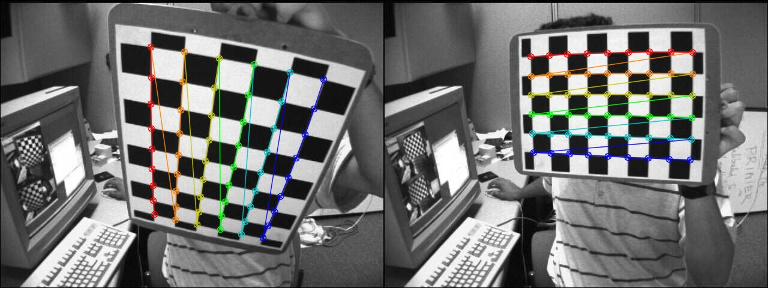
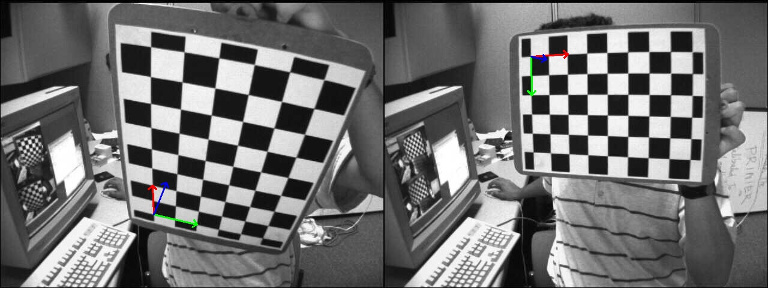
The function findChessboardCorners() returns the chessboard corners location (the left image is the source, the right image is the desired perspective view):

findChessboardCorners

The homography matrix can be estimated with findHomography() or getPerspectiveTransform():

H:
[0.3290339333220102, -1.244138808862929, 536.4769088231476;
 0.6969763913334048, -0.08935909072571532, -80.34068504082408;
 0.00040511729592961, -0.001079740100565012, 0.9999999999999999]

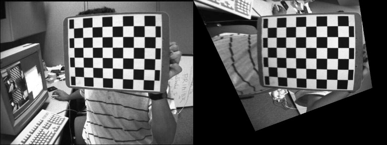
The first image can be warped to the desired perspective view using warpPerspective() (left: desired perspective view, right: left image warped):

warpPerspective


Demo 2: compute the homography matrix from the camera displacement

With the function solvePnP(), we can estimate the camera poses (rvec1, tvec1 and rvec2, tvec2) for the two images and draw the corresponding object frames:

  • Camera pose for the first camera: c1Mo
  • Camera pose for the second camera: c2Mo
  • Homogeneous transformation between the two cameras: c2Mc1

solvePnP

It is then possible to use the camera poses information to compute the homography transformation related to a specific object plane:

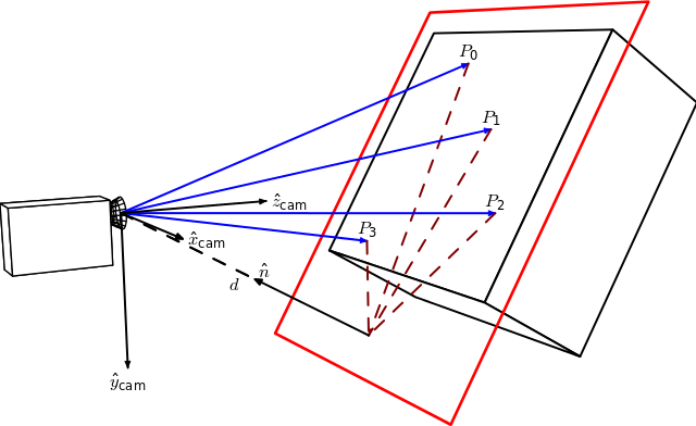
Homography Wikipedia

By Homography-transl.svg: Per Rosengren derivative work: Appoose (Homography-transl.svg) CC BY 3.0, via Wikimedia Commons

On this figure, n is the normal vector of the plane and d the distance between the camera frame and the plane along the plane normal. The equation to compute the homography from the camera displacement is:

Homography from camera displacement

Where H_1to2 is the homography matrix that maps the points in the first camera frame to the corresponding points in the second camera frame, R_1to2 is the rotation matrix that represents the rotation between the two camera frames and t_1to2 the translation vector between the two camera frames.

Here the normal vector n is the plane normal expressed in the camera frame 1 and can be computed as the cross product of 2 vectors (using 3 non collinear points that lie on the plane) or in ...

(more)
edit flag offensive delete link more

Comments

1

@Eduardo, could you push this content into a tutorial on the whole topic. It would be a waste to see this information disappear :/

StevenPuttemans gravatar imageStevenPuttemans ( 2017-04-19 05:07:33 -0600 )edit

what if my camera plane is parallel to image plane, can I assume then homography as identity matrix?

opencvr gravatar imageopencvr ( 2019-06-05 05:27:32 -0600 )edit

If the camera plane is parallel to the planar object, you can describe the transformation using a different model.

If H is identity, it means that there is no transformation, the "images are the same".

Eduardo gravatar imageEduardo ( 2019-06-05 15:30:31 -0600 )edit

could you look at this question link text ? where I have taken R,t as identity matrix, because camera is simply downward to the table where I placed object on different locations on table. is this right method? it is working most of the time.

opencvr gravatar imageopencvr ( 2019-06-07 03:31:22 -0600 )edit

Question Tools

1 follower

Stats

Asked: 2017-03-30 04:19:28 -0600

Seen: 5,546 times

Last updated: Apr 17 '17