read arrow orientation from image
Hello. I created script to get arrows from the image. Im trying to detect orientation for each arrow. With my script i manage to get somewhat accurate results. The problem is that Im getting same results if arrows are oriented up or down, to the left or to the right. How to know if the arrow is pointing to left or to the right? In both cases of the pictures below i get same result around 90 deg.
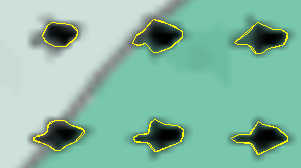
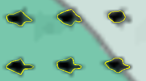
original image

UPDATE 12.12.2016: i manage to get it somewhat working by blurring the picture more to get better contour. I then create bounding rectangle and split it in two parts and calculate surface area of each to get if arrows are facing up or down. Then I chose two points on bounding rectangle and calculate degrees from it. From degrees i then get wind direction.
Now bounding rectangle can sometimes be strangely oriented and giving slightly wrong directions. I think bounding ellipse is more appropriate but the results of degrees are not always correct since i cant set in which direction to check for the angle like i did in rectangle. How could i do the same with ellipse or just mathematically invert degree value based on arrow direction ?
#!/usr/bin/python
import cv2
import numpy as np
from matplotlib import pyplot as plt
import math
import matplotlib.path as mplPath
from math import atan2, degrees, pi


def direction2(img):

    height, width, channels = img.shape
    img = cv2.resize(img, (width*8, height*8))
    img = cv2.medianBlur(img,9)
    imgray = cv2.cvtColor(img,cv2.COLOR_BGR2GRAY)


    ret,th1 = cv2.threshold(imgray,150,255,cv2.THRESH_BINARY)
    edged=cv2.Canny(th1,127,200)
    #return edged


    (img2,cnts, _) = cv2.findContours(edged.copy(), cv2.RETR_TREE, cv2.CHAIN_APPROX_SIMPLE)

    kot=[]
    up_c=0
    down_c=0


    for c in cnts:
        area = cv2.contourArea(c)
        #print area
        cv2.drawContours(img,[c],0,(0,255,0),1)
        if area > 500 and area < 1650:
            #cv2.drawContours(img,[c],0,(0,255,0),1)
            (x,y),radius = cv2.minEnclosingCircle(c)
            center = (int(x),int(y))

            ellipse = cv2.fitEllipse(c)
            (x,y),(MA,ma),angle = cv2.fitEllipse(c)
            #cv2.ellipse(img,ellipse,(0,255,0),1)

            rect = cv2.minAreaRect(c)
            box = cv2.boxPoints(rect)
            box = np.int0(box)
            #print box
            cv2.drawContours(img,[box],0,(0,0,255),1)


            a= math.hypot(box[1][0] - box[0][0], box[1][1] - box[0][1])
            b= math.hypot(box[3][0] - box[0][0], box[3][1] - box[0][1])

            if a>b:
                xos=(box[0][0]+box[1][0])/2
                yos=(box[0][1]+box[1][1])/2
                xos2=(box[2][0]+box[3][0])/2
                yos2=(box[2][1]+box[3][1])/2

                xosa=(box[1][0]+box[2][0])/2
                yosa=(box[1][1]+box[2][1])/2
                xos2a=(box[0][0]+box[3][0])/2
                yos2a=(box[0][1]+box[3][1])/2

                bbPath = mplPath.Path(np.array([[box[0][0], box[0][1]],[xos, yos],[xos2, yos2],[box[3 ...
You might try template matching (if the size and orientation of the arrows is constant) or corner detection using a Harris detector...
i tried template matching with so so results. With the script above the shape is detected just fine. I think it would solve my problem if i would draw bowning rectangle around arrow, split it to two sides by width and then calculate how which one is more filled with contour. The only problem is i don't know how to do it.
Can you share the original Image without any of your marking's?
I updated the question.
It looks like arrow on a map. I think you should try @kbarni answer but with differents template (0 45,90°...). You can try fourier-mellin transform (not included in opencv) too