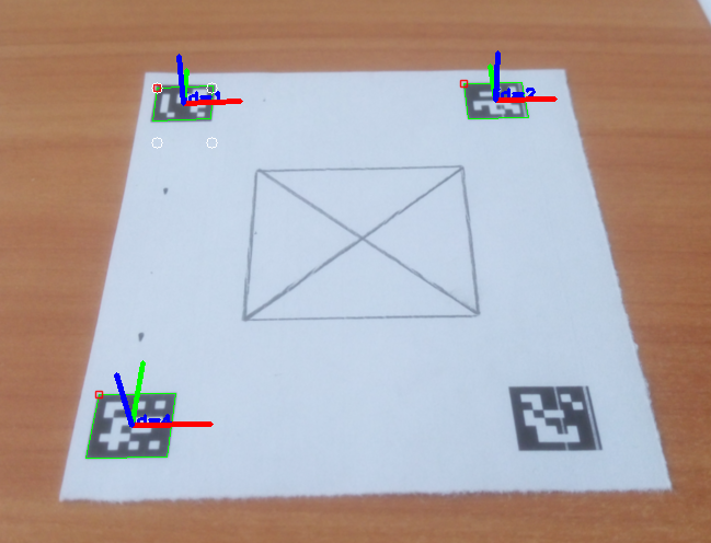
I need to warp the image to fix its perspective distortion based on detected marker. In other words - to get the plane where the marker lays become parallel to the camera plane.
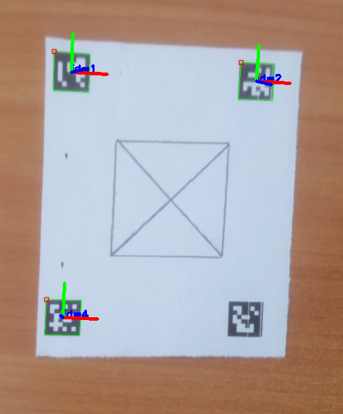
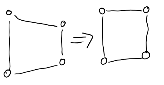
In general it works for me, when I simply map points of perspective-distorted marker to its orthogonal position (Sketch) with getPerspectiveTranfrorm() and then warpPerspective(), which warps whole image:
The following are params for getPerspectiveTransform()
src1 (100, 100) => dst1 (100, 100)
src2 (110, 190) => dst2 (100, 200)
src3: (190, 190) => dst3 (200, 200)
src4: (200, 100) => dst4 (200, 100)
The result looks OK, but not always, so I think that this way is wrong.
My assumption that since for detected marker I can get its pose estimation (which shows its relation to camera) I can calculate required marker position (or camera position?) using marker points and rotation/translation vectors.
Now I'm stuck basically not understanding the math solution. Could you advise?