Turning ArUco marker in parallel with camera plane
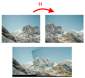
I need to warp the image to fix its perspective distortion based on detected marker. In other words - to get the plane where the marker lays become parallel to the camera plane.
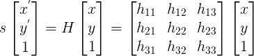
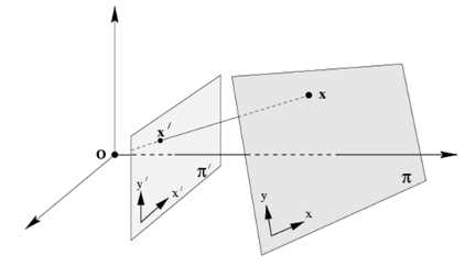
In general it works for me, when I simply map points of perspective-distorted marker to its orthogonal position (Sketch) with getPerspectiveTranfrorm() and then warpPerspective(), which warps whole image:
The following are sample params for getPerspectiveTransform()
src1 (100, 100) => dst1 (100, 100)
src2 (110, 190) => dst2 (100, 200)
src3: (190, 190) => dst3 (200, 200)
src4: (200, 100) => dst4 (200, 100)
The result looks OK, but not always, so I think that this way is wrong.
My assumption that since for detected marker I can get its pose estimation (which shows its relation to camera) I can calculate required marker position (or camera position?) using marker points and rotation/translation vectors.
Now I'm stuck basically not understanding the math solution. Could you advise?
UPDATE
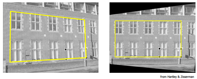
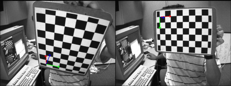
The following is a source image with detected markers. The white circles represent the desired position of marker that will be used in getPerspectiveTransform().
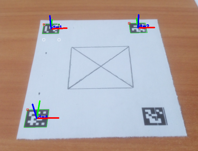
Source corners: [479, 335; 530, 333; 528, 363; 475, 365]
Result corners: [479, 335; 529, 335; 529, 385; 479, 385]
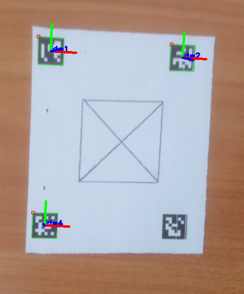
The following is the result image, which is still distorted:
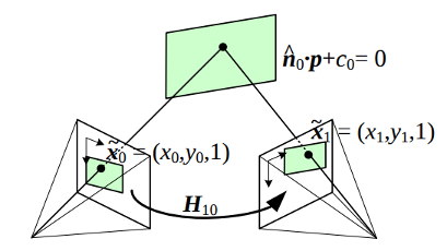
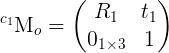
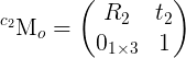

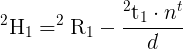
 is the homography matrix that maps the points in the first camera frame to the corresponding points in the second camera frame,
 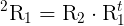 is the rotation matrix that represents the rotation between the two camera frames and
 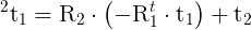 the translation vector between the two camera frames.
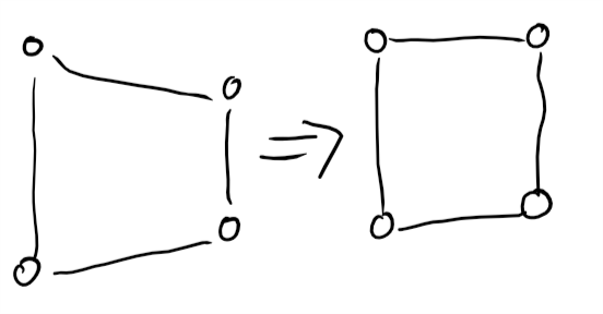
Maybe you can add a sample data: image + extracted corners points in text?
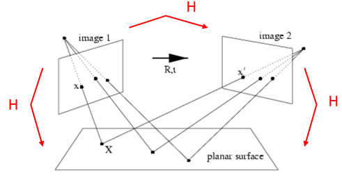
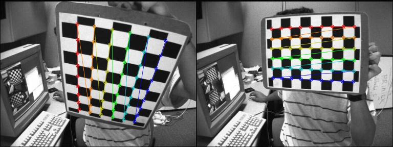
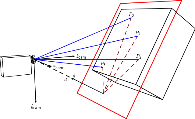
As the marker is planar, the transformation should be a homography. Knowing the two camera poses (current pose estimated and desired camera pose), you should be able to compute the homography matrix from the camera displacement. Once you have the homography, you will have to use
warpPerspective(). You can also compare the two homography matrices.I added source images and corner coordinates. Will read more on homography. Thanks!
I would use rather one or multiple corners but for all the markers to estimate the perspective transformation (you will have to change also the desired coordinates).
Looks like your extracted corner coordinates are integer numbers. Maybe you could check also if you can refine the coordinates of the corners (subpixel accuray, see here in Corner Refinement section) and use
cv::Point2forcv::Point2d.Yes, I plan to switch to subpixel accuracy too. Just wanted first to make sure that I'm not going in wrong direction by not calculating desired coordinates from vectors. I didn't check the homography topic yet though... I believe it will give me more understanding.
I think the issue you have should come from some noise, incertitude in the corner coordinates that will affect the estimation of the perspective transformation. Using points more spread out should lead to better results in my opinion. The original image can also be distorted due to the camera lens and can have an impact somehow.
Note: I think that
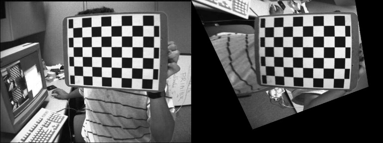
findHomography()orperspectiveTransform()should give you the same transformation matrix, you have to check.I switched to use ARUCO Board and it improved accuracy a lot. findHomography() and getPerspectiveTransform() provide the following result for me.