So basically this small setup illustrates what I want to do:
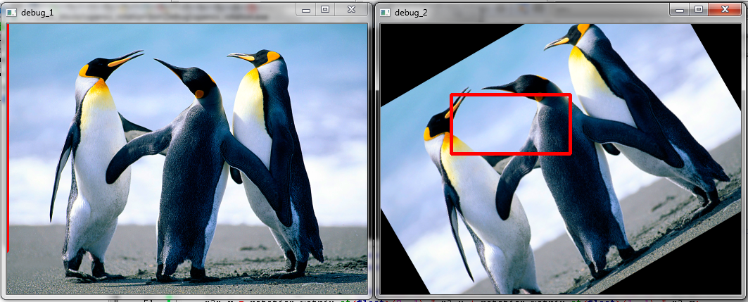
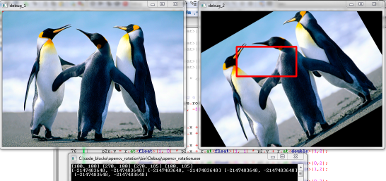
Take image one in the first frame. Imagine this is a patch on whch a cascade model is run. However, the object I am looking for is in the wrong orientation. Imagine that if I rotate this image 30° then a good detection of my model happens.
Now this is good for me, as far as I can reproject the straight rectangle in the rotated image back to a tilted rectangle in the original image. For this I decided to grab the inverse rotation matrix (you can see rows and cols are interchanged) of the first rotation and multiply it with the locations. More info on this process can be found here.
However, as you can see, the reprojected rectangle is wrong. I am trying to figure out why. The link also discusses it is possible to recalculate the locations using sin and cos functions, but it returns the exact wrong parameters for me.
Anyone has an idea?
My code snippet to test this [offcourse replace the image location if you want to test it]:
// SOURCECODE FOR TESTING ROTATION PROPERTIES

#include <opencv2/core/core.hpp>
#include <opencv2/highgui/highgui.hpp>
#include <opencv2/imgproc/imgproc.hpp>

using namespace cv;
using namespace std;

/**
 * Rotate an image around its center point in x and y direction
 * Returns the rotation matrix
 */
Mat rotate( Mat& src, double angle, Mat& dst )
{
    Point2f pt(src.cols/2., src.rows/2.);
    Mat r = getRotationMatrix2D(pt, angle, 1.0);

    warpAffine(src, dst, r, Size(src.cols, src.rows));

    return r;
}

int main()
{
    Mat image = imread("C:/code_blocks/test.jpg", 1);
    resize( image, image, Size(image.cols/2, image.rows/2) );
    Mat image_2 = image.clone();

    // rotate the second image over 30°
    Mat rotation_matrix = rotate(image, 30, image_2);

    // lets fake a rectangle detection on the rotated image around the centerpoint
    Rect detection (100, 100, 170, 85);
    rectangle(image_2, detection, Scalar(0,0,255), 3);

    // hard definition of 4 corner points, warp them back then draw corresponding lines
    Point p1, p2, p3, p4;
    p1.x = detection.x; p1.y = detection.y;
    p2.x = detection.x + detection.width; p2.y = detection.y;
    p3.x = detection.x + detection.width; p3.y = detection.y + detection.height;
    p4.x = detection.x; p4.y = detection.y + detection.height;

    // rotating back the points can be done using the rotation matrix
    // using info on http://stackoverflow.com/questions/6864994/rotating-back-points-from-a-rotated-image-in-opencv
    Point p1n, p2n, p3n, p4n;
    p1n.x = rotation_matrix.at<float>(0, 0) * p1.x + rotation_matrix.at<float>(1, 0) * p1.y;
    p1n.y = rotation_matrix.at<float>(0, 1) * p1.x + rotation_matrix.at<float>(1, 1) * p1.y;

    p2n.x = rotation_matrix.at<float>(0, 0) * p2.x + rotation_matrix.at<float>(1, 0) * p2.y;
    p2n.y = rotation_matrix.at<float>(0, 1) * p2.x + rotation_matrix.at<float>(1, 1) * p2.y;

    p3n.x = rotation_matrix.at<float>(0, 0) * p3.x + rotation_matrix.at<float>(1, 0) * p3.y;
    p3n.y = rotation_matrix.at<float>(0, 1) * p3.x + rotation_matrix.at<float>(1, 1) * p3.y;

    p4n.x = rotation_matrix.at<float>(0, 0) * p4.x + rotation_matrix.at<float>(1, 0) * p4.y;
    p4n.y = rotation_matrix.at<float>(0, 1) * p4.x + rotation_matrix.at<float>(1, 1) * p4.y;

    // Draw the lines on the original image illustrating the transform
    line(image, p1n, p2n, Scalar(0,0,255), 3);
    line(image, p2n, p3n, Scalar(0,0,255), 3);
    line(image, p3n, p4n, Scalar(0,0,255), 3);
    line(image, p4n, p1n, Scalar(0,0,255), 3);

    imshow("debug_1", image); moveWindow("debug_1", 50, 50);
    imshow("debug_2", image_2); moveWindow("debug_2", 50 + image.cols + 50, 50);
    waitKey(0);

    return 0;
}