Ask Your Question
0

Dense optical flow for stitching

asked 2015-04-11 19:28:15 -0600

lcavini gravatar image

updated 2015-04-14 16:10:02 -0600

Hi, I'm trying to stitch some pictures to create a cylindrical panorama with C# and EMGUCV, a wrapper for OpenCV. To do this I want to use a direct-tecnique because I have already tried with a feature-based tecnique (Harris corner detector + pyramid Lucas-Kanade) with good results. I follow these steps for the aligment:

  1. Remap every image in new image by cylindrical equations (as shown in "Image Alignment and Stitching: A Tutorial" by Richard Szeliski).
  2. Estimate optical flow by using a dense algorithm (OpenCV functions: cvCalcOpticalFlowLK or cvCalcOpticalFlowHS)
  3. Using my function to estimate translation vectors based on RANSAC or using OpenCV function "findHomography".

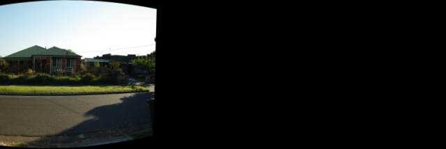
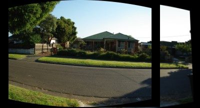
I'm trying with images taken from images set:

image description image description

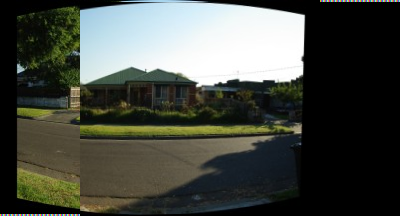
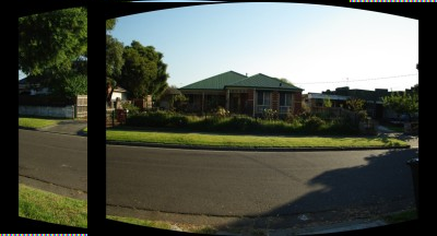
After the 1) step I obtain this: image description image description

After the 3) I obtain this: image description

After optical flow estimation I convert the two returned maps (CvArr* velx, CvArr* vely) describing optical flow in the two directions to two arrays of points filtering flow vectors lower than a value (e.g. < 0.1 pixels). Finally I use findHomography with array of points to estimate the homography (translation). I put here my code to translate maps to array but it's in C# language.

        for (int j = 0; j < vely.Height; j += stepSize)
        {
            for (int i = 0; i < velx.Width; i += stepSize)
            {
                /* There's no need to calculate for every single point,
                if there's not much change, just ignore it */
                if (Math.Abs(velx.Data[j, i, 0]) < minDisplacement_x && Math.Abs(vely.Data[j, i, 0]) < minDisplacement_y)
                    continue;

                sourcePlane[num].X = i;
                sourcePlane[num].Y = j;
                destPlane[num].X = i + velx.Data[j, i, 0];
                destPlane[num].Y = j + vely.Data[j, i, 0];
                num++;
            }
        }
        // Resizes points found array
        System.Array.Resize(ref sourcePlane, num);
        System.Array.Resize(ref destPlane, num);

My problem is about the last step 3). findHomography give me bad results. For example, to estimate about a 100 pixels translation along horizontal direction, the findHomography give me a 2 or 3 pixels translation. I think that the problem is due to the outliers. In fact if I filter the arrays of points before findHomography to delete small vectors of translation by setting min value minDisplacement_x or minDisplacement_y to bigger than 0.1 (e.g. 50.0) the result is a little bit better but not enough. I know that feature-based tecniques are more robust than direct-tecnique but my results are very far from a good solution. Can someone help me? I don't want use feature-based tecnique (features or descriptors or blob) Thanks. Luca

edit retag flag offensive close merge delete

Comments

Have you checked if the optical flow algorithms you are using are actually giving you correct matches? You have images with large texture-less zones, and you are using optical flow method which are intended mostly for short displacement. Also, the remapping which is done before the optical flow may cause bigger errors in the flow computing. You may want to use Brox's method (http://docs.opencv.org/modules/gpu/do...) for the optical flow, and maybe removing large texturless zones. good luck

juanmanpr gravatar imagejuanmanpr ( 2015-04-12 05:42:15 -0600 )edit

Thank you juanmanpr! I know that dense algorithms are very useful with little displacements as you said but I was hoping that using a threshold (setting minDisplacement_x, minDisplacement_y) comparable with the real displacements I can obtaing good results, but unfortunately it's not so. I don't know anything about Brox's method but I will try! Why did you think that the remapping in the step 1) can cause big errors? The optical flow is computed with both images, and both are remapped before.

lcavini gravatar imagelcavini ( 2015-04-13 12:21:58 -0600 )edit

It was just a guess, since apparently they are adding more transformations that the flow should resolve.

juanmanpr gravatar imagejuanmanpr ( 2015-04-14 03:46:41 -0600 )edit

2 answers

Sort by ยป oldest newest most voted
0

answered 2015-04-13 16:29:23 -0600

Eduardo gravatar image

updated 2015-04-13 18:00:40 -0600

Hi,

It is not clear for me if you use findHomography + Ransac or if you try the two approaches independently.

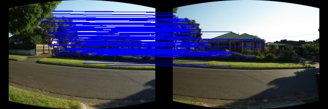
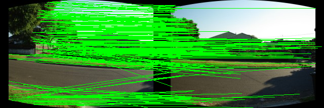
These are my results (not as good as yours but I don't need to threshold the vectors manually, in fact I use the result of findHomography+Ransac to keep the inliers) using calcOpticalFlowPyrLK, findHomography (with CV_RANSAC) and warpPerspective.

Optical flow:

Optical Flow

Inliers:

Inliers

Warp perspective:

Warp

Final image:

Final image

The mean estimated motion (I use the inliers returned by findHomography and I just average the corresponding motion vectors):

Mean x = 80.03 px ; Mean y = 2.18 px

By the way, when you said:

Remap every image in new image by cylindrical equations (as shown in "Image Alignment and Stitching: A Tutorial" by Richard Szeliski).

Is it the section 2.3 Cylindrical and Spherical Coordinates page 15 ?

Edit:

This time I only display the second image with the displacement estimated (no warping).

It is a little bit better I think:

Concat image with displacement vector

Edit2:

I think I made a mistake with warpPerspective: I forgot to inverse the homography H when I applied it to the second image.

The result:

Final image 2

edit flag offensive delete link more
0

answered 2015-04-14 12:14:54 -0600

lcavini gravatar image

Hi Eduardo,

By the way, when you said:

Remap every image in new image by cylindrical equations (as shown in "Image Alignment and Stitching: A Tutorial" by Richard Szeliski).

Is it the section 2.3 Cylindrical and Spherical Coordinates page 15 ?

Yes I was talking about "Cylindrical and spherical coordinates" section. The deformed image that you used are already warped by using those equations.

My results can look like good because two images are overlapped, instead they are very bad! The problem is due to the outliers because as said by juanmanpr optical flow methods (cvCalcOpticalFlowLK or cvCalcOpticalFlowHS) are used when the displacement between two images is little. You are using a feature-based tecnique (calcOpticalFlowPyrLK) with pyramidal version of Lucas-Kanade that is most robust with small and big displacement. And feature methods work for me!

Your last result looks like good but the problem is due to the black zone around the deformed image. When you warps the second image in the plane of the first one you have to "say" to OpenCv to don't consider the black zone but only the image. To do this I create a mask by using the same transformation of the second image on the mask. Finally when I copy the second image in the plane of the first one I use the mask, and that's all!

edit flag offensive delete link more

Comments

So finally what did you use ? calcOpticalFlowPyrLK + findHomography (with RANSAC ?) ? Did you solve your problem ?

Eduardo gravatar imageEduardo ( 2015-04-14 12:53:56 -0600 )edit

No I didn't solve my problem. I'm able to stitch images with calcOpticalFlowPyrLK + findHomography but I want use a dense method like cvCalcOpticalFlowLK + findHomography(with Ransac) or cvCalcOpticalFlowLK + my method to estimate only a translation (not all homography) write using RANSAC. Both ways give me very bad results.

lcavini gravatar imagelcavini ( 2015-04-14 16:08:15 -0600 )edit

Question Tools

3 followers

Stats

Asked: 2015-04-11 19:26:41 -0600

Seen: 4,232 times

Last updated: Apr 14 '15