It will require a cylindrical surface model transform. See this paper for details.
Fortunately, in most cases, you can get by with an approximation by decomposing the transform into two:
- First, perform a flat-surface perspective transform, using the four corners of the card. When rendering the surface, you must render with a generous amount of margin (up to 50% of the image size beyond the boundaries of the original quadrilateral).
- Then, perform a 1D flattening of the dewarped image from the first step. The result from the first step should have straight left and right borders, but curved top and bottom borders. The top and bottom curves may be different. Usually, they are represented as polynomials.
This is just an approximation. If you need a mathematically correct result, you will need another paper.
Keep in mind that for perspective transform, the "center" of the quadrilateral (generally speaking) should be taken to mean the "centroid" of the quadrilateral in mathematical terms. It is the intersection point of the lines AC, BD, which are the two diagonals of the quadrilateral.
Added information:
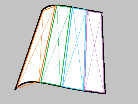
Here is an illustration of the dewarping model:

The bounded area is divided into strips. The vertical boundaries of these strips would have been parallel lines in the word coordinate system (i.e. when measured on the physical object). On the image, these vertical boundaries form a family of lines, which, together with the left and right boundaries of the object, are either coincident at a vanishing point, or are perfectly parallel with each other.
Each strip provides four coordinates (corners) for the dewarping process. In order to generate perspectively correct dewarped result, four correspondence points must be specified. If only two points were given (one from the top curve, another one from the bottom curve), the dewarped pixels will appear distorted and perspectively wrong.


