Ask Your Question
3

Backprojecting detections from a rotated image

asked 2014-02-11 14:51:52 -0600

updated 2015-08-24 09:40:22 -0600

So basically this small setup illustrates what I want to do:
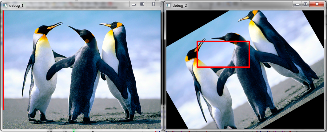
image description

Take image one in the first frame. Imagine this is a patch on whch a cascade model is run. However, the object I am looking for is in the wrong orientation. Imagine that if I rotate this image 30° then a good detection of my model happens.

Now this is good for me, as far as I can reproject the straight rectangle in the rotated image back to a tilted rectangle in the original image. For this I decided to grab the inverse rotation matrix (you can see rows and cols are interchanged) of the first rotation and multiply it with the locations. More info on this process can be found here.

However, as you can see, the reprojected rectangle is wrong. I am trying to figure out why. The link also discusses it is possible to recalculate the locations using sin and cos functions, but it returns the exact wrong parameters for me.

Anyone has an idea?

My code snippet to test this [offcourse replace the image location if you want to test it]:

// SOURCECODE FOR TESTING ROTATION PROPERTIES

#include <opencv2/core/core.hpp>
#include <opencv2/highgui/highgui.hpp>
#include <opencv2/imgproc/imgproc.hpp>

using namespace cv;
using namespace std;

/**
 * Rotate an image around its center point in x and y direction
 * Returns the rotation matrix
 */
Mat rotate( Mat& src, double angle, Mat& dst )
{
    Point2f pt(src.cols/2., src.rows/2.);
    Mat r = getRotationMatrix2D(pt, angle, 1.0);

    warpAffine(src, dst, r, Size(src.cols, src.rows));

    return r;
}

int main()
{
    Mat image = imread("C:/code_blocks/test.jpg", 1);
    resize( image, image, Size(image.cols/2, image.rows/2) );
    Mat image_2 = image.clone();

    // rotate the second image over 30°
    Mat rotation_matrix = rotate(image, 30, image_2);

    // lets fake a rectangle detection on the rotated image around the centerpoint
    Rect detection (100, 100, 170, 85);
    rectangle(image_2, detection, Scalar(0,0,255), 3);

    // hard definition of 4 corner points, warp them back then draw corresponding lines
    Point p1, p2, p3, p4;
    p1.x = detection.x; p1.y = detection.y;
    p2.x = detection.x + detection.width; p2.y = detection.y;
    p3.x = detection.x + detection.width; p3.y = detection.y + detection.height;
    p4.x = detection.x; p4.y = detection.y + detection.height;

    // rotating back the points can be done using the rotation matrix
    // using info on http://stackoverflow.com/questions/6864994/rotating-back-points-from-a-rotated-image-in-opencv
    Point p1n, p2n, p3n, p4n;
    p1n.x = rotation_matrix.at<float>(0, 0) * p1.x + rotation_matrix.at<float>(1, 0) * p1.y;
    p1n.y = rotation_matrix.at<float>(0, 1) * p1.x + rotation_matrix.at<float>(1, 1) * p1.y;

    p2n.x = rotation_matrix.at<float>(0, 0) * p2.x + rotation_matrix.at<float>(1, 0) * p2.y;
    p2n.y = rotation_matrix.at<float>(0, 1) * p2.x + rotation_matrix.at<float>(1, 1) * p2.y;

    p3n.x = rotation_matrix.at<float>(0, 0) * p3.x + rotation_matrix.at<float>(1, 0) * p3.y;
    p3n.y = rotation_matrix.at<float>(0, 1) * p3.x + rotation_matrix.at<float>(1 ...
(more)
edit retag flag offensive close merge delete

1 answer

Sort by » oldest newest most voted
6

answered 2014-02-12 01:13:10 -0600

Haris gravatar image

updated 2014-02-12 10:39:45 -0600

I Just made some change on your code and got fine result, the rotation Mat calculation is according to your UPDATE 2.

Update:

According to documentation the function warpAffine transforms the source image using the specified matrix M by the equation

dst(x,y)=src(M11x+M12y+M13, M21x+M22y+M23)

So, you can translate any point in your source Mat to rotated Mat by multiplying with the corresponding Rotation matrix.

[Transposed Co-ordinates ]  =    [Rotation Mat]    *  [ SRC Co-ordinate ]  


|  _X1   _X2  _X3  _X4  |      |  M11  M12  M13  |   | X1  X2   X3   X4 |     
|                       |   =  |                 | * | Y1  Y2   Y3   Y4 | 
|  _Y1   _Y2  _Y3  _Y4  |      |  M21   M22  M23 |   | 1   1    1    1  |

The same thing you are doing in your code that is expanding the Mat and multiplication, but you are accessing rotation Mat in wrong order, that is your column and rows are interchanged. Also according to the above equation you need to add the last element of rotation Mat to corresponding co-ordinates, and the last thing is change caste float to double.

So just change your code to

    p1n.x = rotation_matrix.at<double>(0, 0) * p1.x + rotation_matrix.at<double>(0, 1) * p1.y+rotation_matrix.at<double>(0, 2); //here row, cols are interchanged in rotation_matrix
    p1n.y = rotation_matrix.at<double>(1, 0) * p1.x + rotation_matrix.at<double>(1, 1) * p1.y+rotation_matrix.at<double>(1, 2); 

    p2n.x = rotation_matrix.at<double>(0, 0) * p2.x + rotation_matrix.at<double>(0, 1) * p2.y+rotation_matrix.at<double>(0, 2);
    p2n.y = rotation_matrix.at<double>(1, 0) * p2.x + rotation_matrix.at<double>(1, 1) * p2.y+rotation_matrix.at<double>(1, 2);

    p3n.x = rotation_matrix.at<double>(0, 0) * p3.x + rotation_matrix.at<double>(0, 1) * p3.y+rotation_matrix.at<double>(0, 2);
    p3n.y = rotation_matrix.at<double>(1, 0) * p3.x + rotation_matrix.at<double>(1, 1) * p3.y+rotation_matrix.at<double>(1, 2);

    p4n.x = rotation_matrix.at<double>(0, 0) * p4.x + rotation_matrix.at<double>(0, 1) * p4.y+rotation_matrix.at<double>(0, 2);
    p4n.y = rotation_matrix.at<double>(1, 0) * p4.x + rotation_matrix.at<double>(1, 1) * p4.y+rotation_matrix.at<double>(1, 2);

Or you can use direct matrix multiplication as shown belwo,

Point    p1n, p2n, p3n, p4n;
// create a new Mat with four co-ordinates
Mat co_Ordinate = (Mat_<double>(3,4) << p1.x, p2.x, p3.x, p4.x,\
                                         p1.y, p2.y, p3.y, p4.y,\
                                         1   , 1  ,  1   , 1    );

Point2f pt(image.cols/2., image.rows/2.);
Mat r = getRotationMatrix2D(pt, -30, 1.0); // Calculate rotation Mat as in your edit
Mat rst=r*co_Ordinate;    // matrix multiplication

// Access transformed co-ordinates from resultant Mat
p1n.x=(int)rst.at<double>(0,0);
p1n.y=(int)rst.at<double>(1,0);

p2n.x=(int)rst.at<double>(0,1);
p2n.y=(int)rst.at<double>(1,1);

p3n.x=(int)rst.at<double>(0,2);
p3n.y=(int)rst.at<double>(1,2);

p4n.x=(int)rst.at<double>(0,3);
p4n.y=(int)rst.at<double>(1,3);

// Draw the lines on ...
(more)
edit flag offensive delete link more

Comments

Nice one! I guess you need to supply points in matrix style to get actual result. I love the fact you just solved my problem, might you have any idea why my approach went crazy?

StevenPuttemans gravatar imageStevenPuttemans ( 2014-02-12 01:43:41 -0600 )edit

See my update....

Haris gravatar imageHaris ( 2014-02-12 04:54:58 -0600 )edit

Thx man! You made my rotation invariant candy detector run smootly :)

StevenPuttemans gravatar imageStevenPuttemans ( 2014-02-12 07:13:21 -0600 )edit

You are welcome ....

Haris gravatar imageHaris ( 2014-02-12 07:16:21 -0600 )edit

Question Tools

1 follower

Stats

Asked: 2014-02-11 14:51:52 -0600

Seen: 1,899 times

Last updated: Feb 12 '14