This forum is disabled, please visit https://forum.opencv.org
| | 1 | initial version |
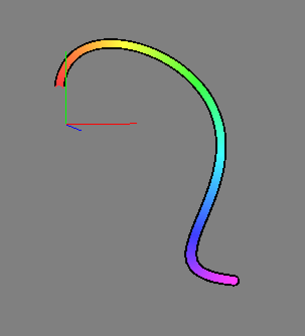
Below is code for a Bezier curve of arbitrary degree (arbitrary number of control points). For instance, I used 2 end points and 3 control points. It's probably as good as a spline.
https://github.com/sjhalayka/bezier_opengl
To make it 2D, just set the z variables to all 0s.
| | 2 | No.2 Revision |
Below is code for a Bezier curve of arbitrary degree (arbitrary number of control points). points) in 3D space. For instance, I used 2 end points and 3 control points. It's probably as good as a spline.
https://github.com/sjhalayka/bezier_opengl
To make it 2D, just set the z variables to all 0s.
| | 3 | No.3 Revision |
Below is code for a Bezier curve of arbitrary degree (arbitrary number of control points) in 3D space. For instance, I used 2 end points and 3 control points. It's probably as good as a spline.
https://github.com/sjhalayka/bezier_opengl
To make it 2D, just set the z variables to all 0s.0s. To add more control points just push_back() onto the vector.
| | 4 | No.4 Revision |
Below is code for a Bezier curve of arbitrary degree (arbitrary number of control points) in 3D space. For instance, I used 2 end points and 3 control points. It's probably as good as a spline.
https://github.com/sjhalayka/bezier_opengl
To make it 2D, just set the z variables to all 0s. To add more control points just push_back() onto the vector.0s.
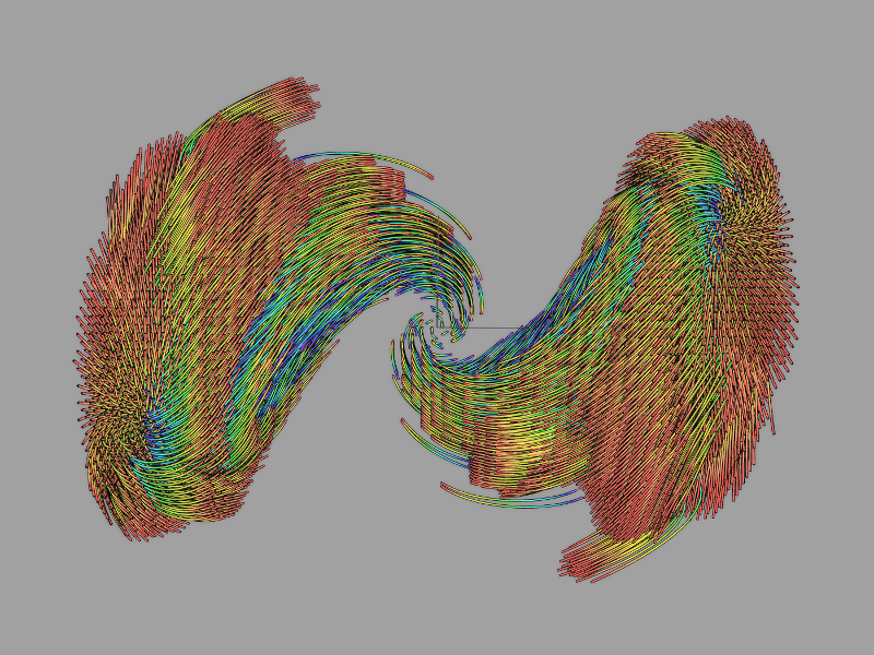
The results can be applied to visualize the escape paths of a quaternion fractal:
| | 5 | No.5 Revision |
Below is code Before you try to get the curved version, why not try the linear version where you can use four triangles and five vertices to represent the height map for a Bezier curve of arbitrary degree (arbitrary number of control points) in 3D space. For instance, I used 2 end points and 3 control points. It's probably as good as a spline.
https://github.com/sjhalayka/bezier_opengl
To make it 2D, just set the z variables to all 0s.
any given four neighbouring pixels.
The results can be applied height of the v0, v1, v2, and v3 vertices are related to visualize the escape paths corresponding pixel intensity. The height of a quaternion fractal:the v5 vertex is the average of the height of the v0, v1, v2, and v3 vertices. The first triangle would have vertices v0, v5, v3. The other three triangles are also made up of three vertices in counterclockwise order.
| | 6 | No.6 Revision |
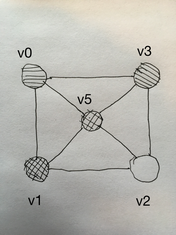
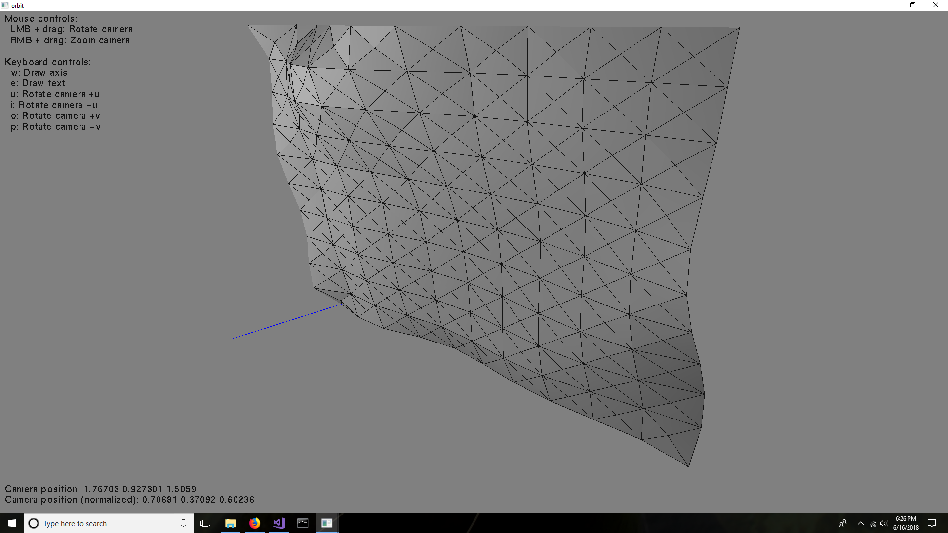
Before you try to get the curved version, why not try the linear version where you can use four triangles and five vertices to represent the height map for any given four neighbouring pixels.
The height of the v0, v1, v2, and v3 vertices are related to the corresponding pixel intensity. The height of the v5 vertex is the average of the height of the v0, v1, v2, and v3 vertices.
The first triangle would have vertices v0, v5, v3. The other three triangles are also made up of three vertices in counterclockwise order.
| | 7 | No.7 Revision |
Before you try to get the curved version, why not try the linear version where you can use four triangles and five vertices to represent the height map for any given four neighbouring pixels.
The height of the v0, v1, v2, and v3 vertices are related to the corresponding pixel intensity. The height of the v5 v4 vertex is the average of the height of the v0, v1, v2, and v3 vertices.
The first triangle would have vertices v0, v5, v4, v3. The other three triangles are also made up of three vertices in counterclockwise order.
| | 8 | No.8 Revision |
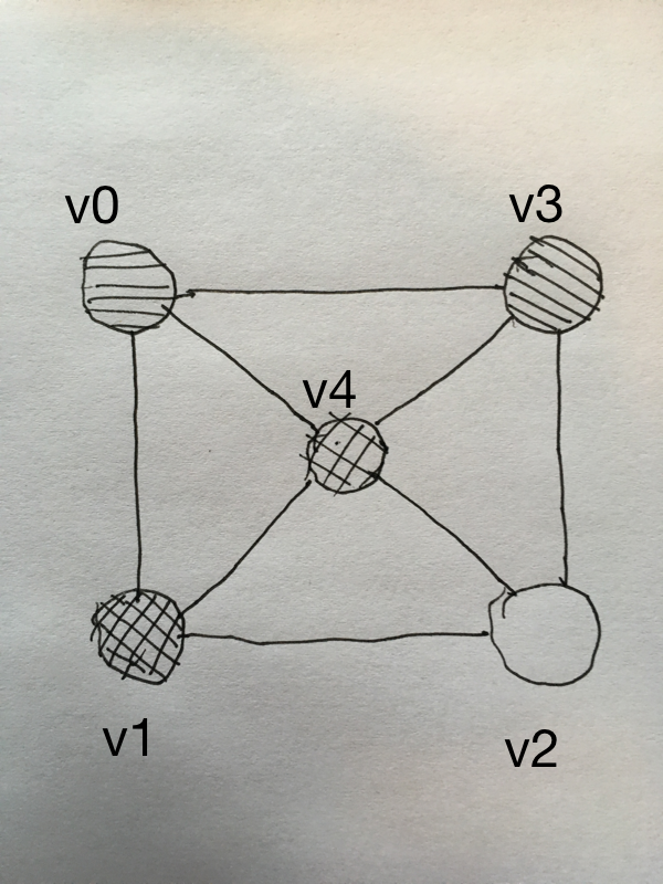
Before you try to get the curved version, why not try the linear version where you can use four triangles and five vertices to represent the height map for any given four neighbouring pixels.
The height of the v0, v1, v2, and v3 vertices are related to the corresponding pixel intensity. The height of the v4 vertex is the average of the height of the v0, v1, v2, and v3 vertices.
The first triangle would have vertices v0, v4, v3. The other three triangles are also made up of three vertices in counterclockwise order.
The code looks like this:
Mat frame = imread("picture.jpg", CV_LOAD_IMAGE_GRAYSCALE);

for (int i = 0; i < frame.cols - 1; i++)
{
    for (int j = 0; j < frame.rows - 1; j++)
    {
        unsigned char intensity0 = frame.at<unsigned char>(j, i);
        unsigned char intensity1 = frame.at<unsigned char>(j + 1, i);
        unsigned char intensity2 = frame.at<unsigned char>(j + 1, i + 1);
        unsigned char intensity3 = frame.at<unsigned char>(j, i + 1);

        unsigned char intensity4 = ((float)intensity0 + (float)intensity1 + (float)intensity2 + (float)intensity3) / 4.0;

        vertex_3 v0(j, i, intensity0 / 255.0 / 10);
        vertex_3 v1(j + 1, i, intensity1 / 255.0 / 10);
        vertex_3 v2(j + 1, i + 1, intensity2 / 255.0 / 10);
        vertex_3 v3(j, i + 1, intensity3 / 255.0 / 10);
        vertex_3 v4((j + j + 1) / 2.0, (i + i + 1) / 2.0, intensity4 / 255.0 / 10);

        v0.x /= 1000;
        v0.y /= 1000;

        v1.x /= 1000;
        v1.y /= 1000;

        v2.x /= 1000;
        v2.y /= 1000;

        v3.x /= 1000;
        v3.y /= 1000;

        v4.x /= 1000;
        v4.y /= 1000;

        triangle t0;
        t0.vertex[0] = v0;
        t0.vertex[1] = v4;
        t0.vertex[2] = v3;

        triangle t1;
        t1.vertex[0] = v0;
        t1.vertex[1] = v1;
        t1.vertex[2] = v4;

        triangle t2;
        t2.vertex[0] = v1;
        t2.vertex[1] = v2;
        t2.vertex[2] = v4;

        triangle t3;
        t3.vertex[0] = v3;
        t3.vertex[1] = v4;
        t3.vertex[2] = v2;

        triangles.push_back(t0);
        triangles.push_back(t1);
        triangles.push_back(t2);
        triangles.push_back(t3);
    }
}

get_vertices_and_normals_from_triangles(triangles, face_normals, vertices, vertex_normals);
| | 9 | No.9 Revision |
Before you try to get the curved version, why not try the linear version where you can use four triangles and five vertices to represent the height map for any given four neighbouring pixels.
The height of the v0, v1, v2, and v3 vertices are related to the corresponding pixel intensity. The height of the v4 vertex is the average of the height of the v0, v1, v2, and v3 vertices.
The first triangle would have vertices v0, v4, v3. The other three triangles are also made up of three vertices in counterclockwise order.
The code looks like this:
Mat frame = imread("picture.jpg", CV_LOAD_IMAGE_GRAYSCALE);

for (int i = 0; i < frame.cols - 1; i++)
{
    for (int j = 0; j < frame.rows - 1; j++)
    {
        unsigned char intensity0 = frame.at<unsigned char>(j, i);
        unsigned char intensity1 = frame.at<unsigned char>(j + 1, i);
        unsigned char intensity2 = frame.at<unsigned char>(j + 1, i + 1);
        unsigned char intensity3 = frame.at<unsigned char>(j, i + 1);

        unsigned char intensity4 = ((float)intensity0 + (float)intensity1 + (float)intensity2 + (float)intensity3) / 4.0;

        vertex_3 v0(j, i, intensity0 / 255.0 / 10);
        vertex_3 v1(j + 1, i, intensity1 / 255.0 / 10);
        vertex_3 v2(j + 1, i + 1, intensity2 / 255.0 / 10);
        vertex_3 v3(j, i + 1, intensity3 / 255.0 / 10);
        vertex_3 v4((j + j + 1) / 2.0, (i + i + 1) / 2.0, intensity4 / 255.0 / 10);

        v0.x /= 1000;
        v0.y /= 1000;

        v1.x /= 1000;
        v1.y /= 1000;

        v2.x /= 1000;
        v2.y /= 1000;

        v3.x /= 1000;
        v3.y /= 1000;

        v4.x /= 1000;
        v4.y /= 1000;

        triangle t0;
        t0.vertex[0] = v0;
        t0.vertex[1] = v4;
        t0.vertex[2] = v3;

        triangle t1;
        t1.vertex[0] = v0;
        t1.vertex[1] = v1;
        t1.vertex[2] = v4;

        triangle t2;
        t2.vertex[0] = v1;
        t2.vertex[1] = v2;
        t2.vertex[2] = v4;

        triangle t3;
        t3.vertex[0] = v3;
        t3.vertex[1] = v4;
        t3.vertex[2] = v2;

        triangles.push_back(t0);
        triangles.push_back(t1);
        triangles.push_back(t2);
        triangles.push_back(t3);
    }
}

get_vertices_and_normals_from_triangles(triangles, face_normals, vertices, vertex_normals);
where:
void get_vertices_and_normals_from_triangles(vector<triangle> &t, vector<vertex_3> &fn, vector<vertex_3> &v, vector<vertex_3> &vn)
{
    fn.clear();
    v.clear();
    vn.clear();

    if(0 == t.size())
        return;

    cout << "Triangles: " << t.size() << endl;

    cout << "Welding vertices" << endl;

    // Insert unique vertices into set.
    set<vertex_3> vertex_set;

    for(vector<triangle>::const_iterator i = t.begin(); i != t.end(); i++)
    {
        vertex_set.insert(i->vertex[0]);
        vertex_set.insert(i->vertex[1]);
        vertex_set.insert(i->vertex[2]);
    }

    cout << "Vertices: " << vertex_set.size() << endl;

    cout << "Generating vertex indices" << endl;

    // Add indices to the vertices.
    for(set<vertex_3>::const_iterator i = vertex_set.begin(); i != vertex_set.end(); i++)
    {
        size_t index = v.size();
        v.push_back(*i);
        v[index].index = index;
    }

    vertex_set.clear();

    // Re-insert modifies vertices into set.
    for(vector<vertex_3>::const_iterator i = v.begin(); i != v.end(); i++)
        vertex_set.insert(*i);

    cout << "Assigning vertex indices to triangles" << endl;

    // Find the three vertices for each triangle, by index.
    set<vertex_3>::iterator find_iter;

    for(vector<triangle>::iterator i = t.begin(); i != t.end(); i++)
    {
        find_iter = vertex_set.find(i->vertex[0]);
        i->vertex[0].index = find_iter->index;

        find_iter = vertex_set.find(i->vertex[1]);
        i->vertex[1].index = find_iter->index;

        find_iter = vertex_set.find(i->vertex[2]);
        i->vertex[2].index = find_iter->index;
    }

    vertex_set.clear();

    cout << "Calculating normals" << endl;
    fn.resize(t.size());
    vn.resize(v.size());

    for(size_t i = 0; i < t.size(); i++)
    {
        vertex_3 v0 = t[i].vertex[1] - t[i].vertex[0];
        vertex_3 v1 = t[i].vertex[2] - t[i].vertex[0];
        fn[i] = v0.cross(v1);
        fn[i].normalize();

        vn[t[i].vertex[0].index] = vn[t[i].vertex[0].index] + fn[i];
        vn[t[i].vertex[1].index] = vn[t[i].vertex[1].index] + fn[i];
        vn[t[i].vertex[2].index] = vn[t[i].vertex[2].index] + fn[i];
    }

    for(size_t i = 0; i < vn.size(); i++)
        vn[i].normalize();
}
The output is hard to visualize:
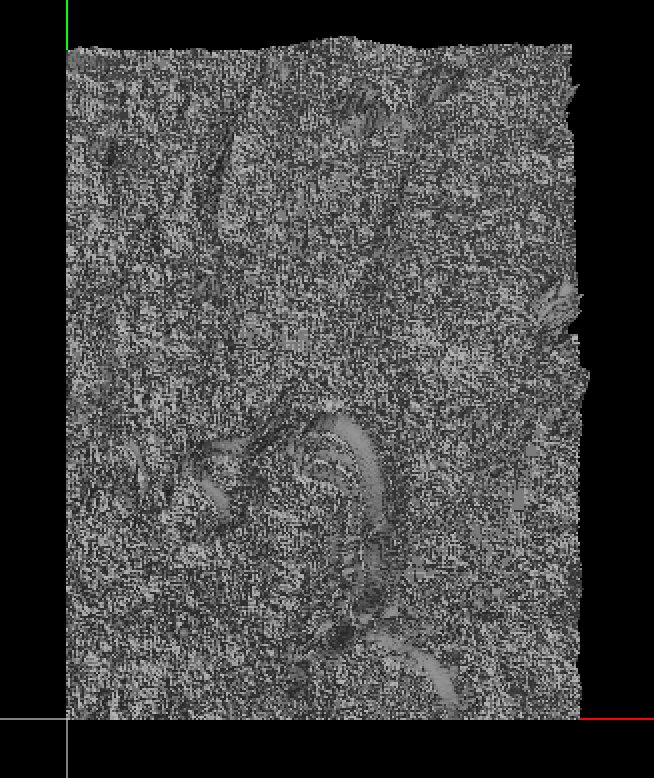
| | 10 | No.10 Revision |
Before you try to get the curved version, why not try the linear version where you can use four triangles and five vertices to represent the height map for any given four neighbouring pixels.
The height of the v0, v1, v2, and v3 vertices are related to the corresponding pixel intensity. The height of the v4 vertex is the average of the height of the v0, v1, v2, and v3 vertices.
The first triangle would have vertices v0, v4, v3. The other three triangles are also made up of three vertices in counterclockwise order.
The code looks like this:
Mat frame = imread("picture.jpg", CV_LOAD_IMAGE_GRAYSCALE);

for (int i = 0; i < frame.cols - 1; i++)
{
    for (int j = 0; j < frame.rows - 1; j++)
    {
        unsigned char intensity0 = frame.at<unsigned char>(j, i);
        unsigned char intensity1 = frame.at<unsigned char>(j + 1, i);
        unsigned char intensity2 = frame.at<unsigned char>(j + 1, i + 1);
        unsigned char intensity3 = frame.at<unsigned char>(j, i + 1);

        unsigned char intensity4 = ((float)intensity0 + (float)intensity1 + (float)intensity2 + (float)intensity3) / 4.0;

        vertex_3 v0(j, i, intensity0 / 255.0 / 10);
        vertex_3 v1(j + 1, i, intensity1 / 255.0 / 10);
        vertex_3 v2(j + 1, i + 1, intensity2 / 255.0 / 10);
        vertex_3 v3(j, i + 1, intensity3 / 255.0 / 10);
        vertex_3 v4((j + j + 1) / 2.0, (i + i + 1) / 2.0, intensity4 / 255.0 / 10);

        v0.x /= 1000;
        v0.y /= 1000;

        v1.x /= 1000;
        v1.y /= 1000;

        v2.x /= 1000;
        v2.y /= 1000;

        v3.x /= 1000;
        v3.y /= 1000;

        v4.x /= 1000;
        v4.y /= 1000;

        triangle t0;
        t0.vertex[0] = v0;
        t0.vertex[1] = v4;
        t0.vertex[2] = v3;

        triangle t1;
        t1.vertex[0] = v0;
        t1.vertex[1] = v1;
        t1.vertex[2] = v4;

        triangle t2;
        t2.vertex[0] = v1;
        t2.vertex[1] = v2;
        t2.vertex[2] = v4;

        triangle t3;
        t3.vertex[0] = v3;
        t3.vertex[1] = v4;
        t3.vertex[2] = v2;

        triangles.push_back(t0);
        triangles.push_back(t1);
        triangles.push_back(t2);
        triangles.push_back(t3);
    }
}

get_vertices_and_normals_from_triangles(triangles, face_normals, vertices, vertex_normals);
where:
void get_vertices_and_normals_from_triangles(vector<triangle> &t, vector<vertex_3> &fn, vector<vertex_3> &v, vector<vertex_3> &vn)
{
    fn.clear();
    v.clear();
    vn.clear();

    if(0 == t.size())
        return;

    cout << "Triangles: " << t.size() << endl;

    cout << "Welding vertices" << endl;

    // Insert unique vertices into set.
    set<vertex_3> vertex_set;

    for(vector<triangle>::const_iterator i = t.begin(); i != t.end(); i++)
    {
        vertex_set.insert(i->vertex[0]);
        vertex_set.insert(i->vertex[1]);
        vertex_set.insert(i->vertex[2]);
    }

    cout << "Vertices: " << vertex_set.size() << endl;

    cout << "Generating vertex indices" << endl;

    // Add indices to the vertices.
    for(set<vertex_3>::const_iterator i = vertex_set.begin(); i != vertex_set.end(); i++)
    {
        size_t index = v.size();
        v.push_back(*i);
        v[index].index = index;
    }

    vertex_set.clear();

    // Re-insert modifies vertices into set.
    for(vector<vertex_3>::const_iterator i = v.begin(); i != v.end(); i++)
        vertex_set.insert(*i);

    cout << "Assigning vertex indices to triangles" << endl;

    // Find the three vertices for each triangle, by index.
    set<vertex_3>::iterator find_iter;

    for(vector<triangle>::iterator i = t.begin(); i != t.end(); i++)
    {
        find_iter = vertex_set.find(i->vertex[0]);
        i->vertex[0].index = find_iter->index;

        find_iter = vertex_set.find(i->vertex[1]);
        i->vertex[1].index = find_iter->index;

        find_iter = vertex_set.find(i->vertex[2]);
        i->vertex[2].index = find_iter->index;
    }

    vertex_set.clear();

    cout << "Calculating normals" << endl;
    fn.resize(t.size());
    vn.resize(v.size());

    for(size_t i = 0; i < t.size(); i++)
    {
        vertex_3 v0 = t[i].vertex[1] - t[i].vertex[0];
        vertex_3 v1 = t[i].vertex[2] - t[i].vertex[0];
        fn[i] = v0.cross(v1);
        fn[i].normalize();

        vn[t[i].vertex[0].index] = vn[t[i].vertex[0].index] + fn[i];
        vn[t[i].vertex[1].index] = vn[t[i].vertex[1].index] + fn[i];
        vn[t[i].vertex[2].index] = vn[t[i].vertex[2].index] + fn[i];
    }

    for(size_t i = 0; i < vn.size(); i++)
        vn[i].normalize();
}
The output is hard to visualize:
| | 11 | No.11 Revision |
Before you try to get the curved version, why not try the linear version where you can use four triangles and five vertices to represent the height map for any given four neighbouring pixels.
The height of the v0, v1, v2, and v3 vertices are related to the corresponding pixel intensity. The height of the v4 vertex is the average of the height of the v0, v1, v2, and v3 vertices.
The first triangle would have vertices v0, v4, v3. The other three triangles are also made up of three vertices in counterclockwise order.
The code looks like this:
Mat frame = imread("picture.jpg", CV_LOAD_IMAGE_GRAYSCALE);

for (int i = 0; i < frame.cols - 1; i++)
{
    for (int j = 0; j < frame.rows - 1; j++)
{
    for (int i = 0; i < frame.cols - 1; i++)
    {
        unsigned char intensity0 = frame.at<unsigned char>(j, i);
        unsigned char intensity1 = frame.at<unsigned char>(j + 1, i);
        unsigned char intensity2 = frame.at<unsigned char>(j + 1, i + 1);
        unsigned char intensity3 = frame.at<unsigned char>(j, i + 1);

        unsigned char intensity4 = ((float)intensity0 + (float)intensity1 + (float)intensity2 (float) intensity2 + (float)intensity3) / 4.0;

        vertex_3 v0(j, i, intensity0 / 255.0 / 10);
50);
        vertex_3 v1(j + 1, i, intensity1 / 255.0 / 10);
50);
        vertex_3 v2(j + 1, i + 1, intensity2 / 255.0 / 10);
50);
        vertex_3 v3(j, i + 1, intensity3 / 255.0 / 10);
50);
        vertex_3 v4((j + j + 1) / 2.0, 2.0 , (i + i + 1) / 2.0, intensity4 / 255.0 / 10);
50);

        v0.x /= 1000;
        1000; v0.y /= 1000;
         v1.x /= 1000;
        1000; v1.y /= 1000;
         v2.x /= 1000;
        1000; v2.y /= 1000;
         v3.x /= 1000;
        1000; v3.y /= 1000;
         v4.x /= 1000;
        1000; v4.y /= 1000;

        triangle t0;
        t0.vertex[0] = v0;
        t0.vertex[1] = v4;
        t0.vertex[2] = v3;
        t0.colour[0].x = intensity0 / 255.0;
        t0.colour[0].y = intensity0 / 255.0;
        t0.colour[0].z = intensity0 / 255.0;
        t0.colour[1].x = intensity4 / 255.0;
        t0.colour[1].y = intensity4 / 255.0;
        t0.colour[1].z = intensity4 / 255.0;
        t0.colour[2].x = intensity3 / 255.0;
        t0.colour[2].y = intensity3 / 255.0;
        t0.colour[2].z = intensity3 / 255.0;

        triangle t1;
        t1.vertex[0] = v0;
        t1.vertex[1] = v1;
        t1.vertex[2] = v4;
        t1.colour[0].x = intensity0 / 255.0;
        t1.colour[0].y = intensity0 / 255.0;
        t1.colour[0].z = intensity0 / 255.0;
        t1.colour[1].x = intensity1 / 255.0;
        t1.colour[1].y = intensity1 / 255.0;
        t1.colour[1].z = intensity1 / 255.0;
        t1.colour[2].x = intensity4 / 255.0;
        t1.colour[2].y = intensity4 / 255.0;
        t1.colour[2].z = intensity4 / 255.0;

        triangle t2;
        t2.vertex[0] = v1;
        t2.vertex[1] = v2;
        t2.vertex[2] = v4;
        t2.colour[0].x = intensity1 / 255.0;
        t2.colour[0].y = intensity1 / 255.0;
        t2.colour[0].z = intensity1 / 255.0;
        t2.colour[1].x = intensity2 / 255.0;
        t2.colour[1].y = intensity2 / 255.0;
        t2.colour[1].z = intensity2 / 255.0;
        t2.colour[2].x = intensity4 / 255.0;
        t2.colour[2].y = intensity4 / 255.0;
        t2.colour[2].z = intensity4 / 255.0;

        triangle t3;
        t3.vertex[0] = v3;
        t3.vertex[1] = v4;
        t3.vertex[2] = v2;
        t3.colour[0].x = intensity3 / 255.0;
        t3.colour[0].y = intensity3 / 255.0;
        t3.colour[0].z = intensity3 / 255.0;
        t3.colour[1].x = intensity4 / 255.0;
        t3.colour[1].y = intensity4 / 255.0;
        t3.colour[1].z = intensity4 / 255.0;
        t3.colour[2].x = intensity2 / 255.0;
        t3.colour[2].y = intensity2 / 255.0;
        t3.colour[2].z = intensity2 / 255.0;

        triangles.push_back(t0);
        triangles.push_back(t1);
        triangles.push_back(t2);
        triangles.push_back(t3);
    }
}

get_vertices_and_normals_from_triangles(triangles, face_normals, vertices, vertex_normals);
where:
void get_vertices_and_normals_from_triangles(vector<triangle> &t, vector<vertex_3> &fn, vector<vertex_3> &v, vector<vertex_3> &vn)
{
    fn.clear();
    v.clear();
    vn.clear();

    if(0 == t.size())
        return;

    cout << "Triangles: " << t.size() << endl;

    cout << "Welding vertices" << endl;

    // Insert unique vertices into set.
    set<vertex_3> vertex_set;

    for(vector<triangle>::const_iterator i = t.begin(); i != t.end(); i++)
    {
        vertex_set.insert(i->vertex[0]);
        vertex_set.insert(i->vertex[1]);
        vertex_set.insert(i->vertex[2]);
    }

    cout << "Vertices: " << vertex_set.size() << endl;

    cout << "Generating vertex indices" << endl;

    // Add indices to the vertices.
    for(set<vertex_3>::const_iterator i = vertex_set.begin(); i != vertex_set.end(); i++)
    {
        size_t index = v.size();
        v.push_back(*i);
        v[index].index = index;
    }

    vertex_set.clear();

    // Re-insert modifies vertices into set.
    for(vector<vertex_3>::const_iterator i = v.begin(); i != v.end(); i++)
        vertex_set.insert(*i);

    cout << "Assigning vertex indices to triangles" << endl;

    // Find the three vertices for each triangle, by index.
    set<vertex_3>::iterator find_iter;

    for(vector<triangle>::iterator i = t.begin(); i != t.end(); i++)
    {
        find_iter = vertex_set.find(i->vertex[0]);
        i->vertex[0].index = find_iter->index;

        find_iter = vertex_set.find(i->vertex[1]);
        i->vertex[1].index = find_iter->index;

        find_iter = vertex_set.find(i->vertex[2]);
        i->vertex[2].index = find_iter->index;
    }

    vertex_set.clear();

    cout << "Calculating normals" << endl;
    fn.resize(t.size());
    vn.resize(v.size());

    for(size_t i = 0; i < t.size(); i++)
    {
        vertex_3 v0 = t[i].vertex[1] - t[i].vertex[0];
        vertex_3 v1 = t[i].vertex[2] - t[i].vertex[0];
        fn[i] = v0.cross(v1);
        fn[i].normalize();

        vn[t[i].vertex[0].index] = vn[t[i].vertex[0].index] + fn[i];
        vn[t[i].vertex[1].index] = vn[t[i].vertex[1].index] + fn[i];
        vn[t[i].vertex[2].index] = vn[t[i].vertex[2].index] + fn[i];
    }

    for(size_t i = 0; i < vn.size(); i++)
        vn[i].normalize();
}
The output is hard to visualize:is:
| | 12 | No.12 Revision |
Before you try to get the curved version, why not try the linear version where you can use four triangles and five vertices to represent the height map for any given four neighbouring pixels.
The height of the v0, v1, v2, and v3 vertices are related to the corresponding pixel intensity. The height of the v4 vertex is the average of the height of the v0, v1, v2, and v3 vertices.
The first triangle would have vertices v0, v4, v3. The other three triangles are also made up of three vertices in counterclockwise order.
The code looks like this:
Mat frame = imread("picture.jpg", CV_LOAD_IMAGE_GRAYSCALE);
transpose(frame, frame);

for (int j = 0; j < frame.rows - 1; j++)
{
    for (int i = 0; i < frame.cols - 1; i++)
    {
        unsigned char intensity0 = frame.at<unsigned char>(j, i);
        unsigned char intensity1 = frame.at<unsigned char>(j + 1, i);
        unsigned char intensity2 = frame.at<unsigned char>(j + 1, i + 1);
        unsigned char intensity3 = frame.at<unsigned char>(j, i + 1);

        unsigned char intensity4 = ((float)intensity0 + (float)intensity1 + (float) intensity2 + (float)intensity3) / 4.0;

        vertex_3 v0(j, i, intensity0 / 255.0 / 50);
        vertex_3 v1(j + 1, i, intensity1 / 255.0 / 50);
        vertex_3 v2(j + 1, i + 1, intensity2 / 255.0 / 50);
        vertex_3 v3(j, i + 1, intensity3 / 255.0 / 50);
        vertex_3 v4((j + j + 1) / 2.0 , (i + i + 1) / 2.0, intensity4 / 255.0 / 50);

        v0.x /= 1000; v0.y /= 1000;
        v1.x /= 1000; v1.y /= 1000;
        v2.x /= 1000; v2.y /= 1000;
        v3.x /= 1000; v3.y /= 1000;
        v4.x /= 1000; v4.y /= 1000;

        triangle t0;
        t0.vertex[0] = v0;
        t0.vertex[1] = v4;
        t0.vertex[2] = v3;
        t0.colour[0].x = intensity0 / 255.0;
        t0.colour[0].y = intensity0 / 255.0;
        t0.colour[0].z = intensity0 / 255.0;
        t0.colour[1].x = intensity4 / 255.0;
        t0.colour[1].y = intensity4 / 255.0;
        t0.colour[1].z = intensity4 / 255.0;
        t0.colour[2].x = intensity3 / 255.0;
        t0.colour[2].y = intensity3 / 255.0;
        t0.colour[2].z = intensity3 / 255.0;

        triangle t1;
        t1.vertex[0] = v0;
        t1.vertex[1] = v1;
        t1.vertex[2] = v4;
        t1.colour[0].x = intensity0 / 255.0;
        t1.colour[0].y = intensity0 / 255.0;
        t1.colour[0].z = intensity0 / 255.0;
        t1.colour[1].x = intensity1 / 255.0;
        t1.colour[1].y = intensity1 / 255.0;
        t1.colour[1].z = intensity1 / 255.0;
        t1.colour[2].x = intensity4 / 255.0;
        t1.colour[2].y = intensity4 / 255.0;
        t1.colour[2].z = intensity4 / 255.0;

        triangle t2;
        t2.vertex[0] = v1;
        t2.vertex[1] = v2;
        t2.vertex[2] = v4;
        t2.colour[0].x = intensity1 / 255.0;
        t2.colour[0].y = intensity1 / 255.0;
        t2.colour[0].z = intensity1 / 255.0;
        t2.colour[1].x = intensity2 / 255.0;
        t2.colour[1].y = intensity2 / 255.0;
        t2.colour[1].z = intensity2 / 255.0;
        t2.colour[2].x = intensity4 / 255.0;
        t2.colour[2].y = intensity4 / 255.0;
        t2.colour[2].z = intensity4 / 255.0;

        triangle t3;
        t3.vertex[0] = v3;
        t3.vertex[1] = v4;
        t3.vertex[2] = v2;
        t3.colour[0].x = intensity3 / 255.0;
        t3.colour[0].y = intensity3 / 255.0;
        t3.colour[0].z = intensity3 / 255.0;
        t3.colour[1].x = intensity4 / 255.0;
        t3.colour[1].y = intensity4 / 255.0;
        t3.colour[1].z = intensity4 / 255.0;
        t3.colour[2].x = intensity2 / 255.0;
        t3.colour[2].y = intensity2 / 255.0;
        t3.colour[2].z = intensity2 / 255.0;

        triangles.push_back(t0);
        triangles.push_back(t1);
        triangles.push_back(t2);
        triangles.push_back(t3);
    }
}

get_vertices_and_normals_from_triangles(triangles, face_normals, vertices, vertex_normals);
where:
void get_vertices_and_normals_from_triangles(vector<triangle> &t, vector<vertex_3> &fn, vector<vertex_3> &v, vector<vertex_3> &vn)
{
    fn.clear();
    v.clear();
    vn.clear();

    if(0 == t.size())
        return;

    cout << "Triangles: " << t.size() << endl;

    cout << "Welding vertices" << endl;

    // Insert unique vertices into set.
    set<vertex_3> vertex_set;

    for(vector<triangle>::const_iterator i = t.begin(); i != t.end(); i++)
    {
        vertex_set.insert(i->vertex[0]);
        vertex_set.insert(i->vertex[1]);
        vertex_set.insert(i->vertex[2]);
    }

    cout << "Vertices: " << vertex_set.size() << endl;

    cout << "Generating vertex indices" << endl;

    // Add indices to the vertices.
    for(set<vertex_3>::const_iterator i = vertex_set.begin(); i != vertex_set.end(); i++)
    {
        size_t index = v.size();
        v.push_back(*i);
        v[index].index = index;
    }

    vertex_set.clear();

    // Re-insert modifies vertices into set.
    for(vector<vertex_3>::const_iterator i = v.begin(); i != v.end(); i++)
        vertex_set.insert(*i);

    cout << "Assigning vertex indices to triangles" << endl;

    // Find the three vertices for each triangle, by index.
    set<vertex_3>::iterator find_iter;

    for(vector<triangle>::iterator i = t.begin(); i != t.end(); i++)
    {
        find_iter = vertex_set.find(i->vertex[0]);
        i->vertex[0].index = find_iter->index;

        find_iter = vertex_set.find(i->vertex[1]);
        i->vertex[1].index = find_iter->index;

        find_iter = vertex_set.find(i->vertex[2]);
        i->vertex[2].index = find_iter->index;
    }

    vertex_set.clear();

    cout << "Calculating normals" << endl;
    fn.resize(t.size());
    vn.resize(v.size());

    for(size_t i = 0; i < t.size(); i++)
    {
        vertex_3 v0 = t[i].vertex[1] - t[i].vertex[0];
        vertex_3 v1 = t[i].vertex[2] - t[i].vertex[0];
        fn[i] = v0.cross(v1);
        fn[i].normalize();

        vn[t[i].vertex[0].index] = vn[t[i].vertex[0].index] + fn[i];
        vn[t[i].vertex[1].index] = vn[t[i].vertex[1].index] + fn[i];
        vn[t[i].vertex[2].index] = vn[t[i].vertex[2].index] + fn[i];
    }

    for(size_t i = 0; i < vn.size(); i++)
        vn[i].normalize();
}
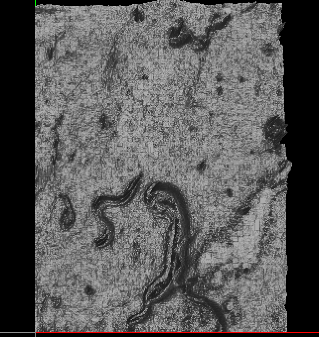
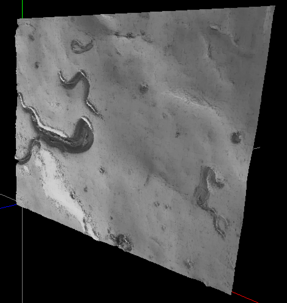
The output is:
| | 13 | No.13 Revision |
Before you try to get the curved version, why not try the linear version where you can use four triangles and five vertices to represent the height map for any given four neighbouring pixels.
The height of the v0, v1, v2, and v3 vertices are related to the corresponding pixel intensity. The height of the v4 vertex is the average of the height of the v0, v1, v2, and v3 vertices.
The first triangle would have vertices v0, v4, v3. The other three triangles are also made up of three vertices in counterclockwise order.
The code looks like this:
Mat frame = imread("picture.jpg", CV_LOAD_IMAGE_GRAYSCALE);
transpose(frame, frame);
flip(frame, frame, 1);

for (int j = 0; j < frame.rows - 1; j++)
{
    for (int i = 0; i < frame.cols - 1; i++)
    {
        unsigned char intensity0 = frame.at<unsigned char>(j, i);
        unsigned char intensity1 = frame.at<unsigned char>(j + 1, i);
        unsigned char intensity2 = frame.at<unsigned char>(j + 1, i + 1);
        unsigned char intensity3 = frame.at<unsigned char>(j, i + 1);

        unsigned char intensity4 = ((float)intensity0 + (float)intensity1 + (float) intensity2 + (float)intensity3) / 4.0;

        vertex_3 v0(j, i, intensity0 / 255.0 / 50);
        vertex_3 v1(j + 1, i, intensity1 / 255.0 / 50);
        vertex_3 v2(j + 1, i + 1, intensity2 / 255.0 / 50);
        vertex_3 v3(j, i + 1, intensity3 / 255.0 / 50);
        vertex_3 v4((j + j + 1) / 2.0 , (i + i + 1) / 2.0, intensity4 / 255.0 / 50);

        v0.x /= 1000; v0.y /= 1000;
        v1.x /= 1000; v1.y /= 1000;
        v2.x /= 1000; v2.y /= 1000;
        v3.x /= 1000; v3.y /= 1000;
        v4.x /= 1000; v4.y /= 1000;

        triangle t0;
        t0.vertex[0] = v0;
        t0.vertex[1] = v4;
        t0.vertex[2] = v3;
        t0.colour[0].x = intensity0 / 255.0;
        t0.colour[0].y = intensity0 / 255.0;
        t0.colour[0].z = intensity0 / 255.0;
        t0.colour[1].x = intensity4 / 255.0;
        t0.colour[1].y = intensity4 / 255.0;
        t0.colour[1].z = intensity4 / 255.0;
        t0.colour[2].x = intensity3 / 255.0;
        t0.colour[2].y = intensity3 / 255.0;
        t0.colour[2].z = intensity3 / 255.0;

        triangle t1;
        t1.vertex[0] = v0;
        t1.vertex[1] = v1;
        t1.vertex[2] = v4;
        t1.colour[0].x = intensity0 / 255.0;
        t1.colour[0].y = intensity0 / 255.0;
        t1.colour[0].z = intensity0 / 255.0;
        t1.colour[1].x = intensity1 / 255.0;
        t1.colour[1].y = intensity1 / 255.0;
        t1.colour[1].z = intensity1 / 255.0;
        t1.colour[2].x = intensity4 / 255.0;
        t1.colour[2].y = intensity4 / 255.0;
        t1.colour[2].z = intensity4 / 255.0;

        triangle t2;
        t2.vertex[0] = v1;
        t2.vertex[1] = v2;
        t2.vertex[2] = v4;
        t2.colour[0].x = intensity1 / 255.0;
        t2.colour[0].y = intensity1 / 255.0;
        t2.colour[0].z = intensity1 / 255.0;
        t2.colour[1].x = intensity2 / 255.0;
        t2.colour[1].y = intensity2 / 255.0;
        t2.colour[1].z = intensity2 / 255.0;
        t2.colour[2].x = intensity4 / 255.0;
        t2.colour[2].y = intensity4 / 255.0;
        t2.colour[2].z = intensity4 / 255.0;

        triangle t3;
        t3.vertex[0] = v3;
        t3.vertex[1] = v4;
        t3.vertex[2] = v2;
        t3.colour[0].x = intensity3 / 255.0;
        t3.colour[0].y = intensity3 / 255.0;
        t3.colour[0].z = intensity3 / 255.0;
        t3.colour[1].x = intensity4 / 255.0;
        t3.colour[1].y = intensity4 / 255.0;
        t3.colour[1].z = intensity4 / 255.0;
        t3.colour[2].x = intensity2 / 255.0;
        t3.colour[2].y = intensity2 / 255.0;
        t3.colour[2].z = intensity2 / 255.0;

        triangles.push_back(t0);
        triangles.push_back(t1);
        triangles.push_back(t2);
        triangles.push_back(t3);
    }
}

get_vertices_and_normals_from_triangles(triangles, face_normals, vertices, vertex_normals);
where:
void get_vertices_and_normals_from_triangles(vector<triangle> &t, vector<vertex_3> &fn, vector<vertex_3> &v, vector<vertex_3> &vn)
{
    fn.clear();
    v.clear();
    vn.clear();

    if(0 == t.size())
        return;

    cout << "Triangles: " << t.size() << endl;

    cout << "Welding vertices" << endl;

    // Insert unique vertices into set.
    set<vertex_3> vertex_set;

    for(vector<triangle>::const_iterator i = t.begin(); i != t.end(); i++)
    {
        vertex_set.insert(i->vertex[0]);
        vertex_set.insert(i->vertex[1]);
        vertex_set.insert(i->vertex[2]);
    }

    cout << "Vertices: " << vertex_set.size() << endl;

    cout << "Generating vertex indices" << endl;

    // Add indices to the vertices.
    for(set<vertex_3>::const_iterator i = vertex_set.begin(); i != vertex_set.end(); i++)
    {
        size_t index = v.size();
        v.push_back(*i);
        v[index].index = index;
    }

    vertex_set.clear();

    // Re-insert modifies vertices into set.
    for(vector<vertex_3>::const_iterator i = v.begin(); i != v.end(); i++)
        vertex_set.insert(*i);

    cout << "Assigning vertex indices to triangles" << endl;

    // Find the three vertices for each triangle, by index.
    set<vertex_3>::iterator find_iter;

    for(vector<triangle>::iterator i = t.begin(); i != t.end(); i++)
    {
        find_iter = vertex_set.find(i->vertex[0]);
        i->vertex[0].index = find_iter->index;

        find_iter = vertex_set.find(i->vertex[1]);
        i->vertex[1].index = find_iter->index;

        find_iter = vertex_set.find(i->vertex[2]);
        i->vertex[2].index = find_iter->index;
    }

    vertex_set.clear();

    cout << "Calculating normals" << endl;
    fn.resize(t.size());
    vn.resize(v.size());

    for(size_t i = 0; i < t.size(); i++)
    {
        vertex_3 v0 = t[i].vertex[1] - t[i].vertex[0];
        vertex_3 v1 = t[i].vertex[2] - t[i].vertex[0];
        fn[i] = v0.cross(v1);
        fn[i].normalize();

        vn[t[i].vertex[0].index] = vn[t[i].vertex[0].index] + fn[i];
        vn[t[i].vertex[1].index] = vn[t[i].vertex[1].index] + fn[i];
        vn[t[i].vertex[2].index] = vn[t[i].vertex[2].index] + fn[i];
    }

    for(size_t i = 0; i < vn.size(); i++)
        vn[i].normalize();
}
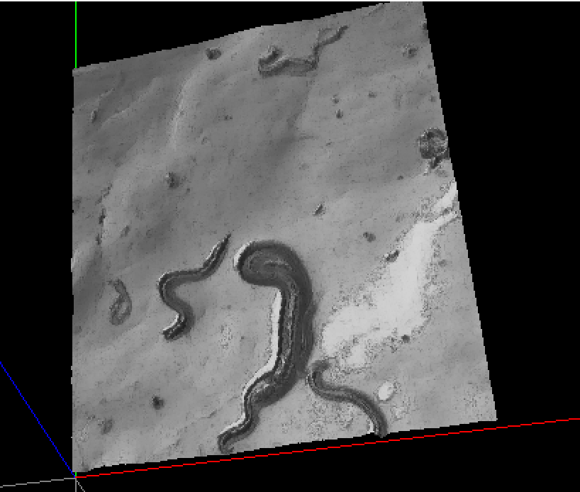
The output is:
| | 14 | No.14 Revision |
Before you try to get the curved version, why not try the linear version where you can use four triangles and five vertices to represent the height map for any given four neighbouring pixels.
The height of the v0, v1, v2, and v3 vertices are related to the corresponding pixel intensity. The height of the v4 vertex is the average of the height of the v0, v1, v2, and v3 vertices.
The first triangle would have vertices v0, v4, v3. The other three triangles are also made up of three vertices in counterclockwise order.
The code looks like this:
Mat frame = imread("picture.jpg", CV_LOAD_IMAGE_GRAYSCALE);
transpose(frame, frame);
flip(frame, frame, 1);

for (int j = 0; j < frame.rows - 1; j++)
{
    for (int i = 0; i < frame.cols - 1; i++)
    {
        unsigned char intensity0 = frame.at<unsigned char>(j, i);
        unsigned char intensity1 = frame.at<unsigned char>(j + 1, i);
        unsigned char intensity2 = frame.at<unsigned char>(j + 1, i + 1);
        unsigned char intensity3 = frame.at<unsigned char>(j, i + 1);

        unsigned char intensity4 = ((float)intensity0 + (float)intensity1 + (float) intensity2 + (float)intensity3) / 4.0;

        vertex_3 v0(j, i, intensity0 / 255.0 / 50);
        vertex_3 v1(j + 1, i, intensity1 / 255.0 / 50);
        vertex_3 v2(j + 1, i + 1, intensity2 / 255.0 / 50);
        vertex_3 v3(j, i + 1, intensity3 / 255.0 / 50);
        vertex_3 v4((j + j + 1) / 2.0 , (i + i + 1) / 2.0, intensity4 / 255.0 / 50);

        v0.x /= 1000; v0.y /= 1000;
        v1.x /= 1000; v1.y /= 1000;
        v2.x /= 1000; v2.y /= 1000;
        v3.x /= 1000; v3.y /= 1000;
        v4.x /= 1000; v4.y /= 1000;

        triangle t0;
        t0.vertex[0] = v0;
        t0.vertex[1] = v4;
        t0.vertex[2] = v3;
        t0.colour[0].x = intensity0 / 255.0;
        t0.colour[0].y = intensity0 / 255.0;
        t0.colour[0].z = intensity0 / 255.0;
        t0.colour[1].x = intensity4 / 255.0;
        t0.colour[1].y = intensity4 / 255.0;
        t0.colour[1].z = intensity4 / 255.0;
        t0.colour[2].x = intensity3 / 255.0;
        t0.colour[2].y = intensity3 / 255.0;
        t0.colour[2].z = intensity3 / 255.0;

        triangle t1;
        t1.vertex[0] = v0;
        t1.vertex[1] = v1;
        t1.vertex[2] = v4;
        t1.colour[0].x = intensity0 / 255.0;
        t1.colour[0].y = intensity0 / 255.0;
        t1.colour[0].z = intensity0 / 255.0;
        t1.colour[1].x = intensity1 / 255.0;
        t1.colour[1].y = intensity1 / 255.0;
        t1.colour[1].z = intensity1 / 255.0;
        t1.colour[2].x = intensity4 / 255.0;
        t1.colour[2].y = intensity4 / 255.0;
        t1.colour[2].z = intensity4 / 255.0;

        triangle t2;
        t2.vertex[0] = v1;
        t2.vertex[1] = v2;
        t2.vertex[2] = v4;
        t2.colour[0].x = intensity1 / 255.0;
        t2.colour[0].y = intensity1 / 255.0;
        t2.colour[0].z = intensity1 / 255.0;
        t2.colour[1].x = intensity2 / 255.0;
        t2.colour[1].y = intensity2 / 255.0;
        t2.colour[1].z = intensity2 / 255.0;
        t2.colour[2].x = intensity4 / 255.0;
        t2.colour[2].y = intensity4 / 255.0;
        t2.colour[2].z = intensity4 / 255.0;

        triangle t3;
        t3.vertex[0] = v3;
        t3.vertex[1] = v4;
        t3.vertex[2] = v2;
        t3.colour[0].x = intensity3 / 255.0;
        t3.colour[0].y = intensity3 / 255.0;
        t3.colour[0].z = intensity3 / 255.0;
        t3.colour[1].x = intensity4 / 255.0;
        t3.colour[1].y = intensity4 / 255.0;
        t3.colour[1].z = intensity4 / 255.0;
        t3.colour[2].x = intensity2 / 255.0;
        t3.colour[2].y = intensity2 / 255.0;
        t3.colour[2].z = intensity2 / 255.0;

        triangles.push_back(t0);
        triangles.push_back(t1);
        triangles.push_back(t2);
        triangles.push_back(t3);
    }
}

get_vertices_and_normals_from_triangles(triangles, face_normals, vertices, vertex_normals);
where:
void get_vertices_and_normals_from_triangles(vector<triangle> &t, vector<vertex_3> &fn, vector<vertex_3> &v, vector<vertex_3> &vn)
{
    fn.clear();
    v.clear();
    vn.clear();

    if(0 == t.size())
        return;

    cout << "Triangles: " << t.size() << endl;

    cout << "Welding vertices" << endl;

    // Insert unique vertices into set.
    set<vertex_3> vertex_set;

    for(vector<triangle>::const_iterator i = t.begin(); i != t.end(); i++)
    {
        vertex_set.insert(i->vertex[0]);
        vertex_set.insert(i->vertex[1]);
        vertex_set.insert(i->vertex[2]);
    }

    cout << "Vertices: " << vertex_set.size() << endl;

    cout << "Generating vertex indices" << endl;

    // Add indices to the vertices.
    for(set<vertex_3>::const_iterator i = vertex_set.begin(); i != vertex_set.end(); i++)
    {
        size_t index = v.size();
        v.push_back(*i);
        v[index].index = index;
    }

    vertex_set.clear();

    // Re-insert modifies vertices into set.
    for(vector<vertex_3>::const_iterator i = v.begin(); i != v.end(); i++)
        vertex_set.insert(*i);

    cout << "Assigning vertex indices to triangles" << endl;

    // Find the three vertices for each triangle, by index.
    set<vertex_3>::iterator find_iter;

    for(vector<triangle>::iterator i = t.begin(); i != t.end(); i++)
    {
        find_iter = vertex_set.find(i->vertex[0]);
        i->vertex[0].index = find_iter->index;

        find_iter = vertex_set.find(i->vertex[1]);
        i->vertex[1].index = find_iter->index;

        find_iter = vertex_set.find(i->vertex[2]);
        i->vertex[2].index = find_iter->index;
    }

    vertex_set.clear();

    cout << "Calculating normals" << endl;
    fn.resize(t.size());
    vn.resize(v.size());

    for(size_t i = 0; i < t.size(); i++)
    {
        vertex_3 v0 = t[i].vertex[1] - t[i].vertex[0];
        vertex_3 v1 = t[i].vertex[2] - t[i].vertex[0];
        fn[i] = v0.cross(v1);
        fn[i].normalize();

        vn[t[i].vertex[0].index] = vn[t[i].vertex[0].index] + fn[i];
        vn[t[i].vertex[1].index] = vn[t[i].vertex[1].index] + fn[i];
        vn[t[i].vertex[2].index] = vn[t[i].vertex[2].index] + fn[i];
    }

    for(size_t i = 0; i < vn.size(); i++)
        vn[i].normalize();
}
The output is:
| | 15 | No.15 Revision |
Before you try OK, now that it's decided that Bezier surfaces are good enough, here is a link to get the curved version, why not try the linear version where you can use four triangles and five vertices function that needs to represent the height map for any given four neighbouring pixels.be implemented:
The height of the v0, v1, v2, and v3 vertices are related to the corresponding pixel intensity. The height of the v4 vertex is the average of the height of the v0, v1, v2, and v3 vertices. http://paulbourke.net/geometry/bezier/
The first triangle would have vertices v0, v4, v3. The other three triangles In the end, the desired output from OpenGL/GLUT is something like this, where there are also made up of three vertices mountains and valleys in counterclockwise order.
The code looks like this:
Mat frame = imread("picture.jpg", CV_LOAD_IMAGE_GRAYSCALE);
transpose(frame, frame);
flip(frame, frame, 1);

for (int j = 0; j < frame.rows - 1; j++)
{
    for (int i = 0; i < frame.cols - 1; i++)
    {
        unsigned char intensity0 = frame.at<unsigned char>(j, i);
        unsigned char intensity1 = frame.at<unsigned char>(j + 1, i);
        unsigned char intensity2 = frame.at<unsigned char>(j + 1, i + 1);
        unsigned char intensity3 = frame.at<unsigned char>(j, i + 1);

        unsigned char intensity4 = ((float)intensity0 + (float)intensity1 + (float) intensity2 + (float)intensity3) / 4.0;

        vertex_3 v0(j, i, intensity0 / 255.0 / 50);
        vertex_3 v1(j + 1, i, intensity1 / 255.0 / 50);
        vertex_3 v2(j + 1, i + 1, intensity2 / 255.0 / 50);
        vertex_3 v3(j, i + 1, intensity3 / 255.0 / 50);
        vertex_3 v4((j + j + 1) / 2.0 , (i + i + 1) / 2.0, intensity4 / 255.0 / 50);

        v0.x /= 1000; v0.y /= 1000;
        v1.x /= 1000; v1.y /= 1000;
        v2.x /= 1000; v2.y /= 1000;
        v3.x /= 1000; v3.y /= 1000;
        v4.x /= 1000; v4.y /= 1000;

        triangle t0;
        t0.vertex[0] = v0;
        t0.vertex[1] = v4;
        t0.vertex[2] = v3;
        t0.colour[0].x = intensity0 / 255.0;
        t0.colour[0].y = intensity0 / 255.0;
        t0.colour[0].z = intensity0 / 255.0;
        t0.colour[1].x = intensity4 / 255.0;
        t0.colour[1].y = intensity4 / 255.0;
        t0.colour[1].z = intensity4 / 255.0;
        t0.colour[2].x = intensity3 / 255.0;
        t0.colour[2].y = intensity3 / 255.0;
        t0.colour[2].z = intensity3 / 255.0;

        triangle t1;
        t1.vertex[0] = v0;
        t1.vertex[1] = v1;
        t1.vertex[2] = v4;
        t1.colour[0].x = intensity0 / 255.0;
        t1.colour[0].y = intensity0 / 255.0;
        t1.colour[0].z = intensity0 / 255.0;
        t1.colour[1].x = intensity1 / 255.0;
        t1.colour[1].y = intensity1 / 255.0;
        t1.colour[1].z = intensity1 / 255.0;
        t1.colour[2].x = intensity4 / 255.0;
        t1.colour[2].y = intensity4 / 255.0;
        t1.colour[2].z = intensity4 / 255.0;

        triangle t2;
        t2.vertex[0] = v1;
        t2.vertex[1] = v2;
        t2.vertex[2] = v4;
        t2.colour[0].x = intensity1 / 255.0;
        t2.colour[0].y = intensity1 / 255.0;
        t2.colour[0].z = intensity1 / 255.0;
        t2.colour[1].x = intensity2 / 255.0;
        t2.colour[1].y = intensity2 / 255.0;
        t2.colour[1].z = intensity2 / 255.0;
        t2.colour[2].x = intensity4 / 255.0;
        t2.colour[2].y = intensity4 / 255.0;
        t2.colour[2].z = intensity4 / 255.0;

        triangle t3;
        t3.vertex[0] = v3;
        t3.vertex[1] = v4;
        t3.vertex[2] = v2;
        t3.colour[0].x = intensity3 / 255.0;
        t3.colour[0].y = intensity3 / 255.0;
        t3.colour[0].z = intensity3 / 255.0;
        t3.colour[1].x = intensity4 / 255.0;
        t3.colour[1].y = intensity4 / 255.0;
        t3.colour[1].z = intensity4 / 255.0;
        t3.colour[2].x = intensity2 / 255.0;
        t3.colour[2].y = intensity2 / 255.0;
        t3.colour[2].z = intensity2 / 255.0;

        triangles.push_back(t0);
        triangles.push_back(t1);
        triangles.push_back(t2);
        triangles.push_back(t3);
    }
}

get_vertices_and_normals_from_triangles(triangles, face_normals, vertices, vertex_normals);
where:
void get_vertices_and_normals_from_triangles(vector<triangle> &t, vector<vertex_3> &fn, vector<vertex_3> &v, vector<vertex_3> &vn)
{
    fn.clear();
    v.clear();
    vn.clear();

    if(0 == t.size())
        return;

    cout << "Triangles: " << t.size() << endl;

    cout << "Welding vertices" << endl;

    // Insert unique vertices into set.
    set<vertex_3> vertex_set;

    for(vector<triangle>::const_iterator i = t.begin(); i != t.end(); i++)
    {
        vertex_set.insert(i->vertex[0]);
        vertex_set.insert(i->vertex[1]);
        vertex_set.insert(i->vertex[2]);
    }

    cout << "Vertices: " << vertex_set.size() << endl;

    cout << "Generating vertex indices" << endl;

    // Add indices the z axis, and height is proportional to the vertices.
    for(set<vertex_3>::const_iterator i = vertex_set.begin(); i != vertex_set.end(); i++)
    {
        size_t index = v.size();
        v.push_back(*i);
        v[index].index = index;
    }

    vertex_set.clear();

    // Re-insert modifies vertices into set.
    for(vector<vertex_3>::const_iterator i = v.begin(); i != v.end(); i++)
        vertex_set.insert(*i);

    cout << "Assigning vertex indices to triangles" << endl;

    // Find the three vertices for each triangle, by index.
    set<vertex_3>::iterator find_iter;

    for(vector<triangle>::iterator i = t.begin(); i != t.end(); i++)
    {
        find_iter = vertex_set.find(i->vertex[0]);
        i->vertex[0].index = find_iter->index;

        find_iter = vertex_set.find(i->vertex[1]);
        i->vertex[1].index = find_iter->index;

        find_iter = vertex_set.find(i->vertex[2]);
        i->vertex[2].index = find_iter->index;
    }

    vertex_set.clear();

    cout << "Calculating normals" << endl;
    fn.resize(t.size());
    vn.resize(v.size());

    for(size_t i = 0; i < t.size(); i++)
    {
        vertex_3 v0 = t[i].vertex[1] - t[i].vertex[0];
        vertex_3 v1 = t[i].vertex[2] - t[i].vertex[0];
        fn[i] = v0.cross(v1);
        fn[i].normalize();

        vn[t[i].vertex[0].index] = vn[t[i].vertex[0].index] + fn[i];
        vn[t[i].vertex[1].index] = vn[t[i].vertex[1].index] + fn[i];
        vn[t[i].vertex[2].index] = vn[t[i].vertex[2].index] + fn[i];
    }

    for(size_t i = 0; i < vn.size(); i++)
        vn[i].normalize();
}
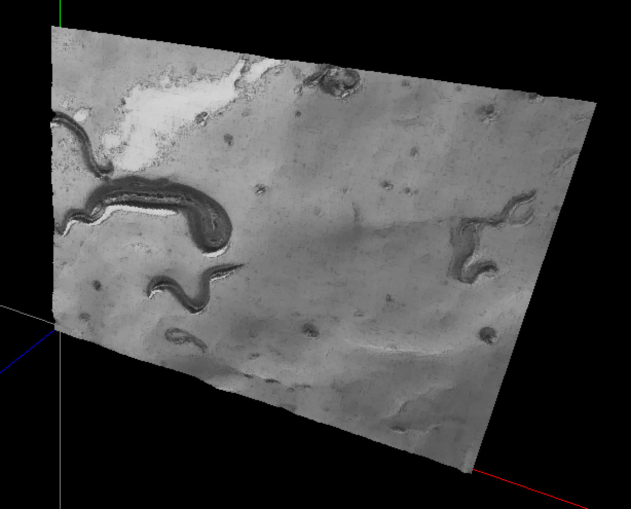
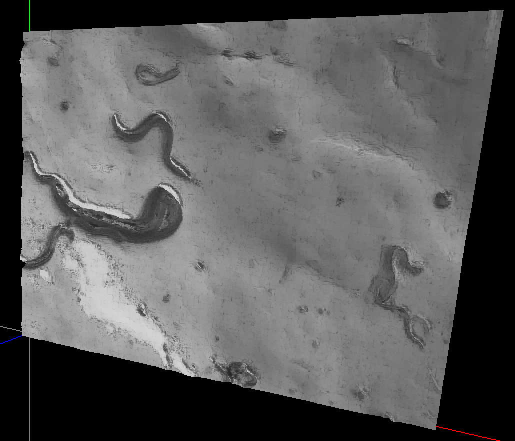
The output is:brightness:
| | 16 | No.16 Revision |
OK, now that it's decided that Bezier surfaces are good enough, here is a link to the function that needs to be implemented:
http://paulbourke.net/geometry/bezier/
In the end, the desired output from OpenGL/GLUT is something like this, where there are mountains and valleys in along the z axis, and the height is proportional to brightness:pixel rightness:
| | 17 | No.17 Revision |
OK, now that it's decided that Bezier surfaces are good enough, here is a link to the function that needs to be implemented:
http://paulbourke.net/geometry/bezier/
I'll look at implementing the function in the next little while.
In the end, the desired output from OpenGL/GLUT is something like this, where there are mountains and valleys along the z axis, and the height is proportional to pixel rightness:
| | 18 | No.18 Revision |
OK, now that it's decided that Bezier surfaces are good enough, here is a link to the function that needs to be implemented:
http://paulbourke.net/geometry/bezier/
I'll look at implementing the function in the next little while.
Here's the code needed for the mathematics behind Bezier surfaces:
long long unsigned int fact(long long unsigned int n)
{
    long long unsigned int ret = 1;

    for(long long unsigned int k = n; k > 0; k--)
        ret *= k;

    return ret;
}

long long unsigned int binomial(long long unsigned int n, long long unsigned int k)
{
    return fact(n) / (fact(k)*fact(n - k));
}
In the end, the desired output from OpenGL/GLUT is something like this, where there are mountains and valleys along the z axis, and the height is proportional to pixel rightness:
| | 19 | No.19 Revision |
OK, now that it's decided that Bezier surfaces are good enough, here is a link to the function that needs to be implemented:
http://paulbourke.net/geometry/bezier/
I'll look at implementing the function in the next little while.
Here's the code needed for the mathematics behind Bezier surfaces:
long long unsigned int fact(long long unsigned int n)
{
    long long unsigned int ret = 1;

    for(long long unsigned int k = n; k > 0; k--)
        ret *= k;

    return ret;
}

long long unsigned int binomial(long long unsigned int n, long long unsigned int k)
{

//     n
// -----------
// k! (n - k)!

    return fact(n) / (fact(k)*fact(n - k));
}
In the end, the desired output from OpenGL/GLUT is something like this, where there are mountains and valleys along the z axis, and the height is proportional to pixel rightness:
| | 20 | No.20 Revision |
OK, now that it's decided that Bezier surfaces are good enough, here is a link to the function that needs to be implemented:
http://paulbourke.net/geometry/bezier/
I'll look at implementing the function in the next little while.
Here's the code needed for the mathematics behind Bezier surfaces:
long long unsigned int fact(long long unsigned int n)
{
    long long unsigned int ret = 1;

    for(long long unsigned int k = n; k > 0; k--)
        ret *= k;

    return ret;
}

long long unsigned int binomial(long long unsigned int n, long long unsigned int k)
{

//     n
n!
// -----------
// k! (n - k)!

    return fact(n) / (fact(k)*fact(n - k));
}
In the end, the desired output from OpenGL/GLUT is something like this, where there are mountains and valleys along the z axis, and the height is proportional to pixel rightness:
| | 21 | No.21 Revision |
OK, now that it's decided that Bezier surfaces are good enough, here is a link to the function that needs to be implemented:
http://paulbourke.net/geometry/bezier/
I'll look at implementing the function in the next little while.
Here's the code needed for the mathematics behind Bezier surfaces:
long long unsigned int fact(long long unsigned int n)
{
    long long unsigned int ret = 1;

    for(long long unsigned int k = n; k > 0; k--)
        ret *= k;

    return ret;
}

long long unsigned int double binomial(long long unsigned int n, long long unsigned int k)
{

//     n!
// -----------
// k! (n - k)!

    return fact(n) long double(fact(n)) / (fact(k)*fact(n long double(fact(k)*fact(n - k));
}
In the end, the desired output from OpenGL/GLUT is something like this, where there are mountains and valleys along the z axis, and the height is proportional to pixel rightness:
| | 22 | No.22 Revision |
OK, now that it's decided that Bezier surfaces are good enough, here is a link to the function that needs to be implemented:
http://paulbourke.net/geometry/bezier/
I'll look at implementing the function in the next little while.
Here's the code needed for the mathematics behind Bezier surfaces:
long long unsigned int fact(long long unsigned int n)
{
    long long unsigned int ret = 1;

    for(long long unsigned int k = n; k > 0; k--)
        ret *= k;

    return ret;
}

long double binomial(long long unsigned int n, long long unsigned int k)
{

//     n!
// -----------
// k! (n - k)!

    return long double(fact(n)) static_cast<long double>(fact(n)) / long double(fact(k)*fact(n static_cast<long double>(fact(k)*fact(n - k));
}
In the end, the desired output from OpenGL/GLUT is something like this, where there are mountains and valleys along the z axis, and the height is proportional to pixel rightness:
| | 23 | No.23 Revision |
OK, now that it's decided that Bezier surfaces are good enough, here is a link to the function that needs to be implemented:
http://paulbourke.net/geometry/bezier/
I'll look at implementing the function in the next little while.
Here's the code needed for the mathematics behind Bezier surfaces:
long long unsigned int fact(long long unsigned int n)
{
    long long unsigned int ret = 1;

    for(long long unsigned int k = n; k > 0; k--)
        ret *= k;

    return ret;
}

long double binomial(long long unsigned int n, long long unsigned int k)
{

//     n!
// -----------
// k! (n - k)!

    return static_cast<long double>(fact(n)) / static_cast<long double>(fact(n))/static_cast<long double>(fact(k)*fact(n - k));
}
In the end, the desired output from OpenGL/GLUT is something like this, where there are mountains and valleys along the z axis, and the height is proportional to pixel rightness:
| | 24 | No.24 Revision |
OK, now that it's decided that Bezier surfaces are good enough, here is a link to the function that needs to be implemented:
http://paulbourke.net/geometry/bezier/
I'll look at implementing the function in the next little while.
Here's Take a look at http://www.purplemath.com/modules/binomial.htm where it shows that the code needed for the mathematics behind Bezier surfaces:formula simplifies to:
long long unsigned int fact(long long unsigned int n)
{
    long long unsigned int ret = 1;

    for(long long unsigned int k = n; k > 0; k--)
        ret *= k;

    return ret;
}

long double binomial(long long unsigned int n, long long unsigned int k)
{

//     n!
// -----------
// k! (n P_ij * (u + (1 - k)!

    return static_cast<long double>(fact(n))/static_cast<long double>(fact(k)*fact(n - k));
}
u))^Ni * (v + (1-v))^Nj
In the end, the desired output from OpenGL/GLUT is something like this, where there are mountains and valleys along the z axis, and the height is proportional to pixel rightness:
| | 25 | No.25 Revision |
OK, now that it's decided that Bezier surfaces are good enough, here is a link to the function that needs to be implemented:
http://paulbourke.net/geometry/bezier/
I'll look at implementing the function in the next little while.
Take a look at http://www.purplemath.com/modules/binomial.htm where it shows that the Bezier formula simplifies to:
P_ij * (u + (1 - u))^Ni * (v + (1-v))^Nj
In the end, the desired output from OpenGL/GLUT is something like this, where there are mountains and valleys along the z axis, and the height is proportional to pixel rightness:
| | 26 | No.26 Revision |
OK, now that it's decided that Bezier surfaces are good enough, here is a link to the function that needs to be implemented:
http://paulbourke.net/geometry/bezier/
I'll look at implementing the function in the next little while.
In the end, the desired output from OpenGL/GLUT is something like this, where there are mountains and valleys along the z axis, and the height is proportional to pixel rightness:brightness:
| | 27 | No.27 Revision |
OK, now that it's decided that Bezier surfaces are good enough, here is a link to the function that needs to be implemented:
http://paulbourke.net/geometry/bezier/
I'll look at implementing I’ve implemented the function function. The code works for very small input images. When the number of control points spirals upward, so does the amount of computation needed. Loading a 1024x1024 image would be only for the very patient.
I’ll polish up the code and post in the next little while.on GitHub ASAP.
In the end, the desired output from OpenGL/GLUT is something like this, where there are mountains and valleys along the z axis, and the height is proportional to pixel brightness:
| | 28 | No.28 Revision |
OK, now that it's decided that Bezier surfaces are good enough, here is a link to the function that needs to be implemented:
http://paulbourke.net/geometry/bezier/
I’ve implemented the function. The code works for very small input images. When the number of control points spirals upward, so does the amount of computation needed. Loading a 1024x1024 image would be only for the very patient.
I’ll polish up the The code and post in on GitHub ASAP.is at https://github.com/sjhalayka/bezier_surface
In Here is a screenshot of the end, the desired output from OpenGL/GLUT is something like this, where there are mountains and valleys along the z axis, and the height is proportional to pixel brightness:curved surface with 16x12 control points.
| | 29 | No.29 Revision |
OK, now that it's decided that Bezier surfaces are good enough, here is a link to the function that needs to be implemented:
http://paulbourke.net/geometry/bezier/
I’ve implemented the function. The code works for very small input images. When the number of control points spirals upward, so does the amount of computation needed. Loading a 1024x1024 image would be only for the very patient.patient. Even then, it appears that the limit is 16x16 before it all blows up.
The code is at https://github.com/sjhalayka/bezier_surface
Here is a screenshot of the curved surface with 16x12 control points.
| | 30 | No.30 Revision |
OK, now that it's decided that Bezier surfaces are good enough, here is a link to the function that needs to be implemented:
http://paulbourke.net/geometry/bezier/
I’ve implemented the function. The code works for very small input images. When the number of control points spirals upward, so does the amount of computation needed. Loading a 1024x1024 image would be only for the very patient. Even then, it appears that the limit is 16x16 before it all blows up.up. My suspicion is that the long double and long long int types aren't large enough.
The code is at https://github.com/sjhalayka/bezier_surface
Here is a screenshot of the curved surface with 16x12 control points.
So, you're better off with the linear version; code at https://github.com/sjhalayka/linear_surface
Below is a screenshot of the surface. No long double or long long int required. Unless you have an arbitrary-sized int and float library, this linear version is literally better than the Bezier surface version, simply because this linear version doesn't blow up at large number of pixels.
| | 31 | No.31 Revision |
OK, now that it's decided that Bezier surfaces are good enough, here is a link to the function that needs to be implemented:
http://paulbourke.net/geometry/bezier/
I’ve implemented the function. The code works for very small input images. When the number of control points spirals upward, so does the amount of computation needed. Loading a 1024x1024 image would be only for the very patient. Even then, it appears that the limit is 16x16 before it all blows up. My suspicion is that the long double and long long int types aren't large enough.
The code is at https://github.com/sjhalayka/bezier_surface
Here is a screenshot of the curved surface with 16x12 control points.
So, you're better off with you might want to try the linear version; code is at https://github.com/sjhalayka/linear_surface
Below is a screenshot of the surface. No long double or long long int required. Unless you have an arbitrary-sized int and float library, this linear version is literally better than the Bezier surface version, simply because this linear version doesn't blow up at large number of pixels.pixels. So, it seems that you need to get something like Boost up and running: https://www.boost.org/doc/libs/1_66_0/libs/multiprecision/doc/html/boost_multiprecision/tut/floats/cpp_dec_float.html
| | 32 | No.32 Revision |
OK, now that it's decided that Bezier surfaces are good enough, here is a link to the function that needs to be implemented:
http://paulbourke.net/geometry/bezier/
I’ve implemented the function. The code works for very small input images. When the number of control points spirals upward, so does the amount of computation needed. Loading a 1024x1024 image would be only for the very patient. Even then, it appears that the limit is 16x16 before it all blows up. My suspicion is that the long double and long long int types aren't large enough.enough. So, it seems that you need to get something like Boost up and running: https://www.boost.org/doc/libs/1_66_0/libs/multiprecision/doc/html/boost_multiprecision/tut/floats/cpp_dec_float.html
The code is at https://github.com/sjhalayka/bezier_surface
Here is a screenshot of the curved surface with 16x12 control points.
So, you might want to try the linear version; code is at https://github.com/sjhalayka/linear_surface
Below is a screenshot of the surface. No long double or long long int required. Unless you have an arbitrary-sized int and float library, this linear version is literally better than the Bezier surface version, simply because this linear version doesn't blow up at large number of pixels. So, it seems that you need to get something like Boost up and running: https://www.boost.org/doc/libs/1_66_0/libs/multiprecision/doc/html/boost_multiprecision/tut/floats/cpp_dec_float.htmlpixels:
| | 33 | No.33 Revision |
OK, now that it's decided that Bezier surfaces are good enough, here is a link to the function that needs to be implemented:
http://paulbourke.net/geometry/bezier/
I’ve implemented the function. The code works for very small input images. When the number of control points spirals upward, so does the amount of computation needed. Loading a 1024x1024 image would be only for the very patient. Even then, it appears that the limit is 16x16 before it all blows up. My suspicion is that the long double and long long int types aren't large enough. So, it seems that you need to get something like Boost up and running: running, to test my hypothesis: https://www.boost.org/doc/libs/1_66_0/libs/multiprecision/doc/html/boost_multiprecision/tut/floats/cpp_dec_float.html
The code is at https://github.com/sjhalayka/bezier_surface
Here is a screenshot of the curved surface with 16x12 control points.
So, you might want to try the linear version; code is at https://github.com/sjhalayka/linear_surface
Below is a screenshot of the surface. No long double or long long int required. Unless you have an arbitrary-sized int and float library, this linear version is literally better than the Bezier surface version, simply because this linear version doesn't blow up at large number of pixels:
| | 34 | No.34 Revision |
OK, now that it's decided that Bezier surfaces are good enough, here is a link to the function that needs to be implemented:
http://paulbourke.net/geometry/bezier/
I’ve implemented the function. The code works for very small input images. When the number of control points spirals upward, so does the amount of computation and variable precision needed. Loading a 1024x1024 image would be only for the very patient. Even then, it appears that the limit is 16x16 before it all blows up. My suspicion is that the long double and long long int types aren't large enough. So, it seems that you need to get something like Boost up and running, to test my hypothesis: https://www.boost.org/doc/libs/1_66_0/libs/multiprecision/doc/html/boost_multiprecision/tut/floats/cpp_dec_float.html
The code is at https://github.com/sjhalayka/bezier_surface
Here is a screenshot of the curved surface with 16x12 control points.
So, you might want to try the linear version; code is at https://github.com/sjhalayka/linear_surface
Below is a screenshot of the surface. No long double or long long int required. Unless you have an arbitrary-sized int and float library, this linear version is literally better than the Bezier surface version, simply because this linear version doesn't blow up at large number of pixels:
| | 35 | No.35 Revision |
OK, now that it's decided that Bezier surfaces are good enough, here is a link to the function that needs to be implemented:
http://paulbourke.net/geometry/bezier/
I’ve implemented the function. The code works for very small input images. When the number of control points spirals upward, so does the amount of computation and variable precision needed. Loading a 1024x1024 image would be only for the very patient. Even then, it appears that the limit is 16x16 before it all blows up. My suspicion is that the long double and long long int types aren't large enough. So, it seems that you need to get something like Boost up and running, to test my hypothesis: https://www.boost.org/doc/libs/1_66_0/libs/multiprecision/doc/html/boost_multiprecision/tut/floats/cpp_dec_float.html
The code is at https://github.com/sjhalayka/bezier_surface
Here is a screenshot of the curved surface with 16x12 control points.
So, since the Bezier surfaces aren't working for now, you might want to try the linear version; version. The code is at https://github.com/sjhalayka/linear_surface
Below is a screenshot of the surface. No long double or long long int required. Unless you have an arbitrary-sized int and float library, this linear version is literally better than the Bezier surface version, simply because this linear version doesn't blow up at large number of pixels:
| | 36 | No.36 Revision |
OK, now that it's decided that Bezier surfaces are good enough, here is a link to the function that needs to be implemented:
http://paulbourke.net/geometry/bezier/
I’ve implemented the function. The code works for very small input images. When the number of control points spirals upward, so does the amount of computation and variable precision needed. Loading a 1024x1024 image would be only for the very patient. Even then, it appears that the limit is 16x16 before it all blows up. My suspicion is that the long double and long long int types aren't large enough. So, it seems that you need to get something like Boost up and running, to test my hypothesis: https://www.boost.org/doc/libs/1_66_0/libs/multiprecision/doc/html/boost_multiprecision/tut/floats/cpp_dec_float.html
The code is at https://github.com/sjhalayka/bezier_surface
Here is a screenshot of the curved surface with 16x12 control points.
So, since the Bezier surfaces aren't working for now, you might want to try the linear version. The code is at https://github.com/sjhalayka/linear_surface
Below is a screenshot of the linear surface. No long double or long long int required. Unless you have an arbitrary-sized int and float library, this linear version is literally better than the Bezier surface version, simply because this linear version doesn't blow up at large number of pixels:
| | 37 | No.37 Revision |
OK, now that it's decided that Bezier surfaces are good enough, here is a link to the function that needs to be implemented:
http://paulbourke.net/geometry/bezier/
I’ve implemented the function. The code works for very small input images. When the number of control points spirals upward, so does the amount of computation and variable precision needed. Loading a 1024x1024 image would be only for the very patient. Even then, it appears that the limit is 16x16 before it all blows up. My suspicion is that the long double and long long int types aren't large enough. So, it seems that you need to get something like Boost multi precision up and running, to test my hypothesis: https://www.boost.org/doc/libs/1_66_0/libs/multiprecision/doc/html/boost_multiprecision/tut/floats/cpp_dec_float.html
The code is at https://github.com/sjhalayka/bezier_surface
Here is a screenshot of the curved surface with 16x12 control points.
So, since the Bezier surfaces aren't working for now, you might want to try the linear version. The code is at https://github.com/sjhalayka/linear_surface
Below is a screenshot of the linear surface. No long double or long long int required. Unless you have an arbitrary-sized int and float library, this linear version is literally better than the Bezier surface version, simply because this linear version doesn't blow up at large number of pixels:
| | 38 | No.38 Revision |
OK, now that it's decided that Bezier surfaces are good enough, here is a link to the function that needs to be implemented:
http://paulbourke.net/geometry/bezier/
I’ve implemented the function. The code works for very small input images. When the number of control points spirals upward, so does the amount of computation and variable precision needed. Loading a 1024x1024 image would be only for the very patient. Even then, it appears that the limit is 16x16 before it all blows up. My suspicion is that the long double and long long int types aren't large enough. So, it seems that you need to get something like Boost multi precision up and running, to test my hypothesis: https://www.boost.org/doc/libs/1_66_0/libs/multiprecision/doc/html/boost_multiprecision/tut/floats/cpp_dec_float.htmlpatient.
The code is at at:
https://github.com/sjhalayka/bezier_surface
Here is a screenshot of the curved surface with 16x12 control points.
So, since the Bezier surfaces aren't working for now, you might want to try the linear version. The code is at https://github.com/sjhalayka/linear_surface
Below is a screenshot of the linear surface. No long double or long long int required. Unless you have an arbitrary-sized int and float library, this linear version is literally better than the Bezier surface version, simply because this linear version doesn't blow up at large number of pixels:
| | 39 | No.39 Revision |
OK, now that it's decided that Bezier surfaces are good enough, here is a link to the function that needs to be implemented:
http://paulbourke.net/geometry/bezier/
I’ve implemented the function. When the number of control points spirals upward, so does the amount of computation and variable precision needed. Loading a 1024x1024 image would be only for the very patient.patient. I had to use the Boost multi precision library, with 100 digits, because long long unsigned int and long double were not big enough.
The code is at:
https://github.com/sjhalayka/bezier_surface
Here is a screenshot of the curved surface with 16x12 control points.points:
| | 40 | No.40 Revision |
OK, now that it's decided that Bezier surfaces are good enough, here is a link to the function that needs to be implemented:
http://paulbourke.net/geometry/bezier/
I’ve implemented the function. When the number of control points spirals upward, so does the amount of computation and variable precision needed. Loading a 1024x1024 image would be only for the very patient. I had to use the Boost multi precision library, with 100 digits, because long long unsigned int and long double were not big enough.enough. If you find that this answer is suitable, please mark it as correct (click on the checkmark).
The code is at:
https://github.com/sjhalayka/bezier_surface
Here is a screenshot of the curved surface with 16x12 control points:
| | 41 | No.41 Revision |
OK, now that it's decided that Bezier surfaces are might be good enough, here is a link to the function that needs to be implemented:
http://paulbourke.net/geometry/bezier/
I’ve implemented the function. When the number of control points spirals upward, so does the amount of computation and variable precision needed. Loading a 1024x1024 image would be only for the very patient. I had to use the Boost multi precision library, with 100 digits, because long long unsigned int and long double were not big enough. If you find that this answer is suitable, please mark it as correct (click on the checkmark).
The code is at:
https://github.com/sjhalayka/bezier_surface
Here is a screenshot of the curved surface with 16x12 control points:
| | 42 | No.42 Revision |
OK, now that it's decided that Bezier surfaces might be good enough, here is a link to the function that needs to be implemented:
http://paulbourke.net/geometry/bezier/
I’ve implemented the function. When the number of control points spirals upward, so does the amount of computation and variable precision needed. Loading a 1024x1024 image would be only for the very patient. I had to use the Boost multi precision library, with 100 digits, because long long unsigned int and long double were not big enough. If you find that this answer is suitable, please mark it as correct (click on the checkmark).
The code is at:
https://github.com/sjhalayka/bezier_surface
Here is a screenshot of the curved surface with 16x12 control points:
The next step is to create a NURBS surface, which is like a Bézier curve, but with a knot vector.
| | 43 | No.43 Revision |
OK, now that it's decided that Bezier surfaces might be good enough, here is a link to the function that needs to be implemented:
http://paulbourke.net/geometry/bezier/
I’ve implemented the function. When the number of control points spirals upward, so does the amount of computation and variable precision needed. Loading a 1024x1024 image would be only for the very patient. I had to use the Boost multi precision library, with 100 digits, because long long unsigned int and long double were not big enough. If you find that this answer is suitable, please mark it as correct (click on the checkmark).
The code is at:
https://github.com/sjhalayka/bezier_surface
Here is a screenshot of the curved surface with 16x12 control points:
The next step is to create a NURBS surface, which is like a Bézier curve, surface, but with a knot vector.
| | 44 | No.44 Revision |
OK, now that it's decided that Bezier surfaces might be good enough, here is a link to the function that needs to be implemented:
http://paulbourke.net/geometry/bezier/
I’ve implemented the function. When the number of control points spirals upward, so does the amount of computation and variable precision needed. Loading a 1024x1024 image would be only for the very patient. I had to use the Boost multi precision library, with 100 digits, because long long unsigned int and long double were not big enough. If you find that this answer is suitable, please mark it as correct (click on the checkmark).
The code is at:
https://github.com/sjhalayka/bezier_surface
Here is a screenshot of the curved surface with 16x12 control points:
The next step is to create a NURBS surface, which is like a Bézier surface, but with a knot vector.vector. I have a feeling that a knot vector of all 1s may do the trick. One dimension per control point. I could very well be wrong.
| | 45 | No.45 Revision |
OK, now that it's decided that Bezier surfaces might be good enough, here is a link to the function that needs to be implemented:
http://paulbourke.net/geometry/bezier/
I’ve implemented the function. When the number of control points spirals upward, so does the amount of computation and variable precision needed. Loading a 1024x1024 image would be only for the very patient. I had to use the Boost multi precision library, with 100 digits, because long long unsigned int and long double were not big enough. If you find that this answer is suitable, please mark it as correct (click on the checkmark).
The code is at:
https://github.com/sjhalayka/bezier_surface
Here is a screenshot of the curved surface with 16x12 control points:
The next step is to create a NURBS surface, which is like a Bézier surface, but with a knot vector. I have a feeling that a knot vector of all 1s or all 0s may do the trick. One dimension per control point. I could very well be wrong.
| | 46 | No.46 Revision |
OK, now that it's decided that Bezier surfaces might be good enough, here is a link to the function that needs to be implemented:
http://paulbourke.net/geometry/bezier/
I’ve implemented the function. When the number of control points spirals upward, so does the amount of computation and variable precision needed. Loading a 1024x1024 image would be only for the very patient. I had to use the Boost multi precision library, with 100 digits, because long long unsigned int and long double were not big enough. If you find that this answer is suitable, please mark it as correct (click on the checkmark).
The code is at:
https://github.com/sjhalayka/bezier_surface
Here is a screenshot of the curved surface with 16x12 control points:
The next step is to create a NURBS surface, which is like a Bézier surface, but with a knot vector. I have a feeling vector, whatever that a knot vector of all 1s or all 0s may do the trick. One dimension per control point. I could very well be wrong.means.
| | 47 | No.47 Revision |
OK, now that it's decided that Bezier surfaces might be good enough, here is a link to the function that needs to be implemented:
http://paulbourke.net/geometry/bezier/
I’ve implemented the function. When the number of control points spirals upward, so does the amount of computation and variable precision needed. Loading a 1024x1024 image would be only for the very patient. I had to use the Boost multi precision library, with 100 digits, because long long unsigned int and long double were not big enough. If you find that this answer is suitable, please mark it as correct (click on the checkmark).
The code is at:
https://github.com/sjhalayka/bezier_surface
Here is a screenshot of the curved surface with 16x12 control points:
The next step is to create a NURBS surface, which is like a Bézier surface, but with a knot vector, vector... whatever that means.
| | 48 | No.48 Revision |
OK, now that it's decided that Bezier surfaces might be good enough, here is a link to the function that needs to be implemented:
http://paulbourke.net/geometry/bezier/
I’ve implemented the function. When the number of control points spirals upward, so does the amount of computation and variable precision needed. Loading a 1024x1024 image would be only for the very patient. I had to use the Boost multi precision library, with 100 digits, because long long unsigned int and long double were not big enough. If you find that this answer is suitable, please mark it as correct (click on the checkmark).
The code is at:
https://github.com/sjhalayka/bezier_surface
Here is a screenshot of the curved surface with 16x12 64x48 control points:

The next step is to create a NURBS surface, which is like a Bézier surface, but with a knot vector... whatever that means.
| | 49 | No.49 Revision |
OK, now that it's decided that Bezier surfaces might be good enough, here is a link to the function that needs to be implemented:
http://paulbourke.net/geometry/bezier/
I’ve implemented the function. When the number of control points spirals upward, so does the amount of computation and variable precision needed. Loading a 1024x1024 image would be only for the very patient. I had to use the Boost multi precision library, with 100 digits, because long long unsigned int and long double were not big enough. If you find that this answer is suitable, please mark it as correct (click on the checkmark).
The code is at:
https://github.com/sjhalayka/bezier_surface
Here is a screenshot of the curved surface with 64x48 control points:points, spacer = 0.01:
The next step is to create a NURBS surface, which is like a Bézier surface, but with a knot vector... whatever that means.
| | 50 | No.50 Revision |
OK, now that it's decided that Bezier surfaces might be good enough, here is a link to the function that needs to be implemented:
http://paulbourke.net/geometry/bezier/
I’ve implemented the function. When the number of control points spirals upward, so does the amount of computation and variable precision needed. Loading a 1024x1024 image would be only for the very patient. I had to use the Boost multi precision library, with 100 digits, because long long unsigned int and long double were not big enough. If you find that this answer is suitable, please mark it as correct (click on the checkmark).
The code is at:
https://github.com/sjhalayka/bezier_surface
Here is a screenshot of the curved surface with 64x48 control points, spacer = 0.01:
The next step is to create a NURBS surface, which is like a Bézier surface, but with a knot vector... whatever that means.
If you are ultimately disappointed in the lack of ability to use large images as Bezier or NURBS control points, then you could always try the linear version, which has no problem handling large images:
https://github.com/sjhalayka/linear_surface
| | 51 | No.51 Revision |
OK, now that it's decided that Bezier surfaces might be good enough, here is a link to the function that needs to be implemented:
http://paulbourke.net/geometry/bezier/
I’ve implemented the function. When the number of control points spirals upward, so does the amount of computation and variable precision needed. Loading a 1024x1024 image would be only for the very patient. I had to use the Boost multi precision library, with 100 digits, because long long unsigned int and long double were not big enough. If you find that this answer is suitable, please mark it as correct (click on the checkmark).
The code is at:
https://github.com/sjhalayka/bezier_surface
Here is a screenshot of the curved surface with 64x48 control points, spacer = 0.01:
The next step is to create a NURBS surface, which is like a Bézier surface, but with a knot vector... whatever that means.
If you are ultimately disappointed in the lack of ability to use large images as Bezier or NURBS control points, then you could always try the linear version, which has no problem handling large images:
https://github.com/sjhalayka/linear_surface
A screenshot of the linear surface with an image of 512x384 pixels is given below:
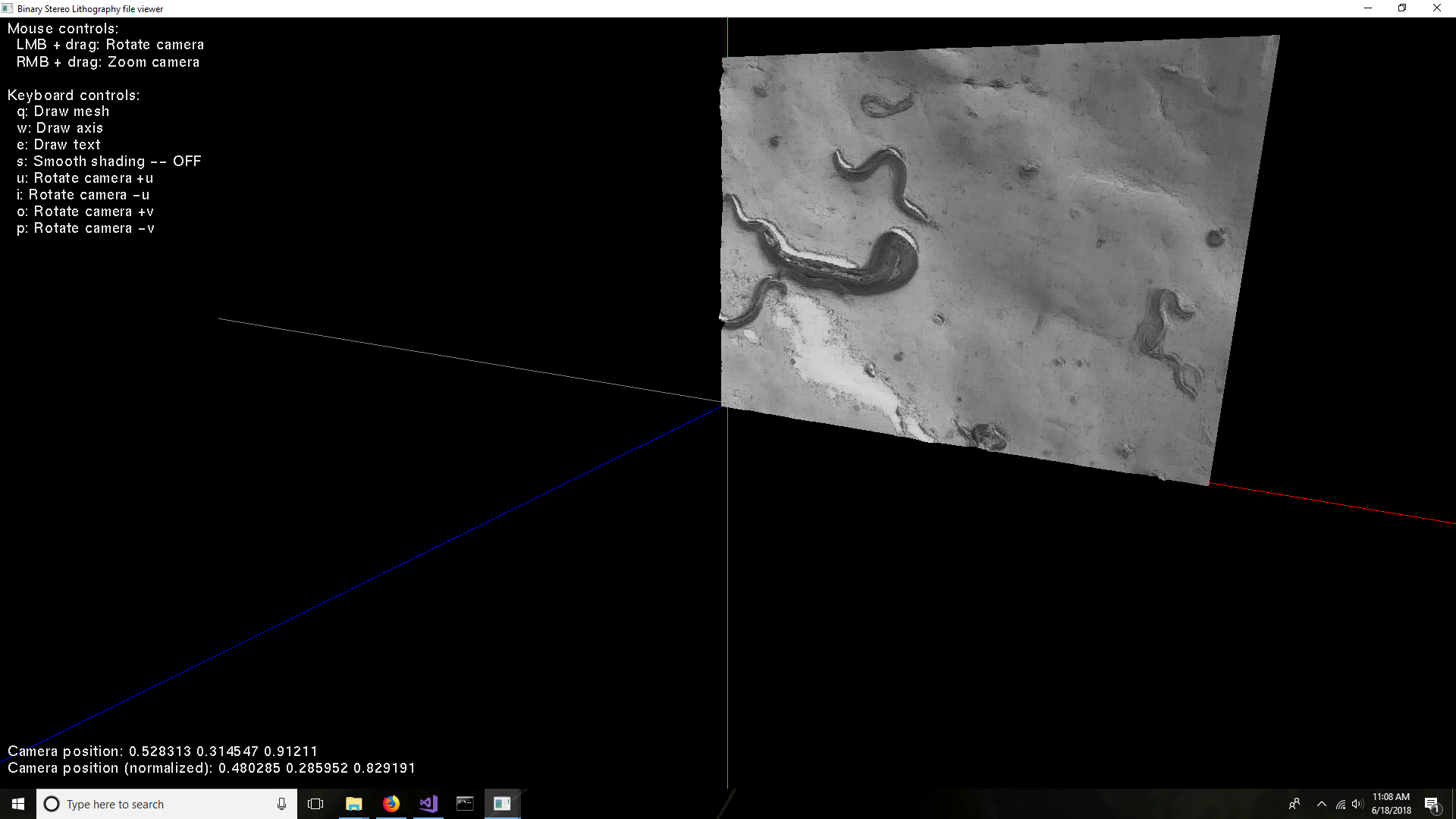
| | 52 | No.52 Revision |
OK, now that it's decided that Bezier surfaces might be good enough, here is a link to the function that needs to be implemented:
http://paulbourke.net/geometry/bezier/
I’ve implemented the function. When the number of control points spirals upward, so does the amount of computation and variable precision needed. Loading a 1024x1024 image would be only for the very patient. I had to use the Boost multi precision library, with 100 digits, because long long unsigned int and long double were not big enough. If you find that this answer is suitable, please mark it as correct (click on the checkmark).
The code is at:
https://github.com/sjhalayka/bezier_surface
Here is a screenshot of the curved surface with 64x48 control points, spacer = 0.01:
The next step is to create a NURBS surface, which is like a Bézier surface, but with a knot vector... whatever that means.
If you are ultimately disappointed in the lack of ability to use large images as Bezier or NURBS control points, then you could always try the linear version, which has no problem handling large images:
https://github.com/sjhalayka/linear_surface
A screenshot of the linear surface with an image of 512x384 pixels "control points" is given below:
| | 53 | No.53 Revision |
OK, now that it's decided that Bezier surfaces might be good enough, here is a link to the function that needs to be implemented:
http://paulbourke.net/geometry/bezier/
I’ve implemented the function. When the number of control points spirals upward, so does the amount of computation and variable precision needed. Loading a 1024x1024 image would be only for the very patient. I had to use the Boost multi precision library, with 100 digits, because long long unsigned int and long double were not big enough. If you find that this answer is suitable, please mark it as correct (click on the checkmark).
The code is at:
https://github.com/sjhalayka/bezier_surface
Here is a screenshot of the curved surface with 64x48 control points, spacer = 0.01:
The next step is to create a NURBS surface, which is like a Bézier surface, but with a knot vector... whatever that means.
If you are ultimately disappointed in the lack of ability to use large images as Bezier or NURBS control points, then you could always try the linear version, which has no problem handling large images:
https://github.com/sjhalayka/linear_surface
A screenshot of the linear surface with an image of 512x384 "control points" is given below:
| | 54 | No.54 Revision |
OK, now that it's decided that Bezier surfaces might be good enough, here is a link to the function that needs to be implemented:
http://paulbourke.net/geometry/bezier/
I’ve implemented the function. When the number of control points spirals upward, so does the amount of computation and variable precision needed. Loading a 1024x1024 image would be only for the very patient. I had to use the Boost multi precision library, with 100 digits, because long long unsigned int and long double were not big enough. If you find that this answer is suitable, please mark it as correct (click on the checkmark).
The code is at:
https://github.com/sjhalayka/bezier_surface
Here is a screenshot of the curved surface with 64x48 control points, spacer = 0.01:
The next step is to create a NURBS surface, which is like a Bézier surface, but with a knot vector... whatever that means.
If you are ultimately disappointed in the lack of ability to use large images as Bezier or NURBS control points, then you could always try the linear version, which has no problem handling large images:
https://github.com/sjhalayka/linear_surface
A screenshot of the linear surface with 512x384 "control points" is given below:below. The colouring uses OpenGL lighting in combination with vertex intensity (which is related to the z value). It's very much like displacement mapping:
| | 55 | No.55 Revision |
OK, now that it's decided that Bezier surfaces might be good enough, here is a link to the function that needs to be implemented:
http://paulbourke.net/geometry/bezier/
I’ve implemented the function. When the number of control points spirals upward, so does the amount of computation and variable precision needed. Loading a 1024x1024 image would be only for the very patient. I had to use the Boost multi precision library, with 100 digits, because long long unsigned int and long double were not big enough. If you find that this answer is suitable, please mark it as correct (click on the checkmark).
The code is at:
https://github.com/sjhalayka/bezier_surface
Here is a screenshot of the curved surface with 64x48 control points, spacer = 0.01:
The next step is to create a NURBS surface, which is like a Bézier surface, but with a knot vector... whatever that means.
If you are ultimately disappointed in the lack of ability to use large images as Bezier or NURBS control points, then you could always try the linear version, which has no problem handling large images:
https://github.com/sjhalayka/linear_surface
A screenshot of the linear surface with 512x384 "control points" is given below. The colouring uses OpenGL lighting in combination with vertex intensity (which is related to the z value). It's very much like displacement mapping:mapping. Ultimately, the linear surface is feasible, where the curved surface is not.
| | 56 | No.56 Revision |
OK, now that it's decided that Bezier surfaces might be good enough, here is a link to the function that needs to be implemented:
http://paulbourke.net/geometry/bezier/
I’ve implemented the function. When the number of control points spirals upward, so does the amount of computation and variable precision needed. Loading a 1024x1024 image would be only for the very patient. I had to use the Boost multi precision library, with 100 digits, because long long unsigned int and long double were not big enough. If you find that this answer is suitable, please mark it as correct (click on the checkmark).
The code is at:
https://github.com/sjhalayka/bezier_surface
Here is a screenshot of the curved surface with 64x48 control points, spacer = 0.01:
The next step is to create a NURBS surface, which is like a Bézier surface, but with a knot vector... whatever that means.
If you are ultimately disappointed in the lack of ability to use large images as Bezier or NURBS control points, then you could always try the linear version, which has no problem handling large images:
https://github.com/sjhalayka/linear_surface
A screenshot of the linear surface with 512x384 "control points" is given below. The colouring uses OpenGL lighting in combination with vertex intensity (which is related to the z value). It's very much like displacement mapping. Ultimately, the linear surface is feasible, where the curved surface is not.not. Best of luck on your work in the future.
| | 57 | No.57 Revision |
OK, now that it's decided that Bezier surfaces might be good enough, here is a link to the function that needs to be implemented:
http://paulbourke.net/geometry/bezier/
I’ve implemented the function. When the number of control points spirals upward, so does the amount of computation and variable precision needed. Loading a 1024x1024 image would be only for the very patient. I had to use the Boost multi precision library, with 100 digits, because long long unsigned int and long double were not big enough. If you find that this answer is suitable, please mark it as correct (click on the checkmark).
The code is at:
https://github.com/sjhalayka/bezier_surface
Here Below is a screenshot of the curved surface with 64x48 control points, spacer = 0.01:0.01. It took roughly an hour to generate on my desktop computer.
The next step is to create a NURBS surface, which is like a Bézier surface, but with a knot vector... whatever that means.
If you are ultimately disappointed in the lack of ability to use large images as Bezier or NURBS control points, then you could always try the linear version, which has no problem handling large images:
https://github.com/sjhalayka/linear_surface
A screenshot of the linear surface with 512x384 "control points" is given below. The colouring uses OpenGL lighting in combination with vertex intensity (which is related to the z value). It's very much like displacement mapping. Ultimately, the linear surface is feasible, where the curved surface is not. Best of luck on your work in the future.
| | 58 | No.58 Revision |
OK, now that it's decided that Bezier surfaces might be good enough, here is a link to the function that needs to be implemented:
http://paulbourke.net/geometry/bezier/
I’ve implemented the function. When the number of control points spirals upward, so does the amount of computation and variable precision needed. Loading a 1024x1024 image would be only for the very patient. I had to use the Boost multi precision library, with 100 digits, because long long unsigned int and long double were not big enough. If you find that this answer is suitable, please mark it as correct (click on the checkmark).
The code is at:
https://github.com/sjhalayka/bezier_surface
Below is a screenshot of the curved surface with 64x48 control points, spacer = 0.01. It took roughly an hour to generate on my desktop computer.
The next step is to create a NURBS surface, which is like a Bézier surface, but with a knot vector... whatever that means.
If you are ultimately disappointed in the lack of ability to use large images as Bezier or NURBS control points, then you could always try the linear version, which has no problem handling large images:
https://github.com/sjhalayka/linear_surface
A screenshot of the linear surface with 512x384 "control points" is given below. The colouring uses OpenGL lighting in combination with vertex intensity (which is related to the z value). It's very much like displacement mapping. Ultimately, the linear surface is feasible, where the curved surface is not. Best of luck It took roughly 5 seconds to generate on your work in the future.my desktop computer.
| | 59 | No.59 Revision |
OK, now that it's decided that Bezier surfaces might be good enough, here is a link to the function that needs to be implemented:
http://paulbourke.net/geometry/bezier/
I’ve implemented the function. When the number of control points spirals upward, so does the amount of computation and variable precision needed. Loading a 1024x1024 image would be only for the very patient. I had to use the Boost multi precision library, with 100 digits, because long long unsigned int and long double were not big enough. If you find that this answer is suitable, please mark it as correct (click on the checkmark).
The code is at:
https://github.com/sjhalayka/bezier_surface
Below is a screenshot of the curved surface with 64x48 control points, spacer = 0.01. It took roughly an hour to generate on my desktop computer.computer. The colouring uses OpenGL lighting in combination with vertex intensity (which is related to the z value). It's very much like displacement mapping.
The next step is to create a NURBS surface, which is like a Bézier surface, but with a knot vector... whatever that means.
If you are ultimately disappointed in the lack of ability to use large images as Bezier or NURBS control points, then you could always try the linear version, which has no problem handling large images:
https://github.com/sjhalayka/linear_surface
A screenshot of the linear surface with 512x384 "control points" is given below. The colouring uses OpenGL lighting in combination with vertex intensity (which is related to the z value). It's very much like displacement mapping. Ultimately, the linear surface is feasible, where the curved surface is not. It took roughly 5 seconds to generate on my desktop computer.
| | 60 | No.60 Revision |
OK, now that it's decided that Bezier surfaces might be good enough, here is a link to the function that needs to be implemented:
http://paulbourke.net/geometry/bezier/
I’ve implemented the function. When the number of control points spirals upward, so does the amount of computation and variable precision needed. Loading a 1024x1024 image would be only for the very patient. I had to use the Boost multi precision library, with 100 digits, because long long unsigned int and long double were not big enough. If you find that this answer is suitable, please mark it as correct (click on the checkmark).
The code is at:
https://github.com/sjhalayka/bezier_surface
Below is a screenshot of the curved surface with 64x48 control points, spacer = 0.01. It took roughly an hour to generate on my desktop computer. The colouring uses OpenGL lighting in combination with vertex intensity (which is related to the z value). It's very much like displacement mapping.
The next step is to create a NURBS surface, which is like a Bézier surface, but with a knot vector... whatever that means.
If you are ultimately disappointed in the lack of ability to use large images as Bezier or NURBS control points, points due to time constraints, then you could always try the linear version, which has no problem handling large images:images.
https://github.com/sjhalayka/linear_surface
A screenshot of the linear surface with 512x384 "control points" is given below. Ultimately, the linear surface is feasible, where the curved surface is not. It took roughly 5 seconds to generate on my desktop computer.
| | 61 | No.61 Revision |
OK, now that it's decided that Bezier surfaces might be good enough, here is a link to the function that needs to be implemented:
http://paulbourke.net/geometry/bezier/
I’ve implemented the function. When the number of control points spirals upward, so does the amount of computation and variable precision needed. Loading a 1024x1024 image would be only for the very patient. I had to use the Boost multi precision library, with 100 digits, because long long unsigned int and long double were not big enough. If you find that this answer is suitable, please mark it as correct (click on the checkmark).
The code is at:
https://github.com/sjhalayka/bezier_surface
Below is a screenshot of the curved surface with 64x48 control points, spacer = 0.01. It took roughly an hour to generate on my desktop computer. The colouring uses OpenGL lighting in combination with vertex intensity (which is related to the z value). It's very much like displacement mapping.
The next step is to create a NURBS surface, which is like a Bézier surface, but with a knot vector... whatever that means.
If you are ultimately disappointed in the lack of ability to use large images as Bezier or NURBS control points due to time constraints, constraints (literally, days and months of processing time), then you could always try the linear version, which has no problem handling large images.
https://github.com/sjhalayka/linear_surface
A screenshot of the linear surface with 512x384 "control points" is given below. Ultimately, the linear surface is feasible, where the curved surface is not. It took roughly 5 seconds to generate on my desktop computer.
| | 62 | No.62 Revision |
OK, now that it's decided that Bezier surfaces might be good enough, here is a link to the function that needs to be implemented:
http://paulbourke.net/geometry/bezier/
I’ve implemented the function. When the number of control points spirals upward, so does the amount of computation and variable precision needed. Loading a 1024x1024 image would be only for the very patient. I had to use the Boost multi precision library, with 100 digits, because long long unsigned int and long double were not big enough. If you find that this answer is suitable, please mark it as correct (click on the checkmark).
The code is at:
https://github.com/sjhalayka/bezier_surface
Below is a screenshot of the curved surface with 64x48 control points, spacer = 0.01. It took roughly an hour to generate on my desktop computer. The colouring uses OpenGL lighting in combination with vertex intensity (which is related to the z value). It's very much like displacement mapping.
The next step is to create a NURBS surface, which is like a Bézier surface, but with a knot vector... whatever that means.
If you are ultimately disappointed in the lack of ability to use large images as Bezier or NURBS control points due to time constraints (literally, days and months of processing time), then you could always try the linear version, which has no problem handling large images.
https://github.com/sjhalayka/linear_surface
A screenshot of the linear surface with 512x384 "control points" is given below. Ultimately, the linear surface is feasible, where the curved surface is not. It took roughly 5 seconds to generate on my desktop computer.computer. This is because it uses only local data to generate the triangles, where in the case of Bezier surfaces, only global data is used to generate the triangles.
| | 63 | No.63 Revision |
OK, now that it's decided that Bezier surfaces might be good enough, here is a link to the function that needs to be implemented:
http://paulbourke.net/geometry/bezier/
I’ve implemented the function. When the number of control points spirals upward, so does the amount of computation and variable precision needed. Loading a 1024x1024 image would be only for the very patient. I had to use the Boost multi precision library, with 100 digits, because long long unsigned int and long double were not big enough. If you find that this answer is suitable, please mark it as correct (click on the checkmark).
The code is at:
https://github.com/sjhalayka/bezier_surface
Below is a screenshot of the curved surface with 64x48 control points, spacer = 0.01. It took roughly an hour to generate on my desktop computer. The colouring uses OpenGL lighting in combination with vertex intensity (which is related to the z value). It's very much like displacement mapping.
The next step is to create a NURBS surface, which is like a Bézier surface, but with a knot vector... whatever that means.
If you are ultimately disappointed in the lack of ability to use large images as Bezier or NURBS control points due to time constraints (literally, days and months of processing time), then you could always try the linear version, which has no problem handling large images.
https://github.com/sjhalayka/linear_surface
A screenshot of the linear surface with 512x384 "control points" is given below. Ultimately, the linear surface is feasible, where the curved surface is not. It took roughly 5 seconds to generate on my desktop computer. This is because it uses only local data to generate the triangles, where in the case of Bezier or NURBS surfaces, only the entire global data is used to generate the triangles.
| | 64 | No.64 Revision |
OK, now that it's decided that Bezier surfaces might be good enough, here is a link to the function that needs to be implemented:
http://paulbourke.net/geometry/bezier/
The function is:
I’ve implemented the function. When the number of control points spirals upward, so does the amount of computation and variable precision needed. Loading a 1024x1024 image would be only for the very patient. I had to use the Boost multi precision library, with 100 digits, because long long unsigned int and long double were not big enough. If you find that this answer is suitable, please mark it as correct (click on the checkmark).
The code is at:
https://github.com/sjhalayka/bezier_surface
Below is a screenshot of the curved surface with 64x48 control points, spacer = 0.01. It took roughly an hour to generate on my desktop computer. The colouring uses OpenGL lighting in combination with vertex intensity (which is related to the z value). It's very much like displacement mapping.
The next step is to create a NURBS surface, which is like a Bézier surface, but with a knot vector... whatever that means.
If you are ultimately disappointed in the lack of ability to use large images as Bezier or NURBS control points due to time constraints (literally, days and months of processing time), then you could always try the linear version, which has no problem handling large images.
https://github.com/sjhalayka/linear_surface
A screenshot of the linear surface with 512x384 "control points" is given below. Ultimately, the linear surface is feasible, where the curved surface is not. It took roughly 5 seconds to generate on my desktop computer. This is because it uses only local data to generate the triangles, where in the case of Bezier or NURBS surfaces, the entire global data is used to generate the triangles.
| | 65 | No.65 Revision |
OK, now that it's decided that Bezier surfaces might be good enough, here is a link to the function that needs to be implemented:
http://paulbourke.net/geometry/bezier/
The function is:
I’ve implemented the function. When the number of control points spirals upward, so does the amount of computation and variable precision needed. Loading a 1024x1024 image would be only for the very patient. I had to use the Boost multi precision library, with 100 digits, because long long unsigned int and long double were not big enough. If you find that this answer is suitable, please mark it as correct (click on the checkmark).
The code is at:
https://github.com/sjhalayka/bezier_surface
Below is a screenshot of the curved surface with 64x48 control points, spacer = 0.01. It took roughly an hour to generate on my desktop computer. The colouring uses OpenGL lighting in combination with vertex intensity (which is related to the z value). It's very much like displacement mapping.
The next step is to create a NURBS surface, which is like a Bézier surface, but with a knot vector... whatever that means.
If you are ultimately disappointed in the lack of ability to use large images as Bezier or NURBS control points due to time constraints (literally, days and months of processing time), then you could always try the linear version, which has no problem handling large images.
https://github.com/sjhalayka/linear_surface
A screenshot of the linear surface with 512x384 "control points" is given below. Ultimately, the linear surface is feasible, where the curved surface is not. It took roughly 5 seconds to generate on my desktop computer. This is because it uses only local data to generate the local triangles, where in the case of Bezier or NURBS surfaces, the entire global data is used to generate the local triangles.
| | 66 | No.66 Revision |
OK, now that it's decided that Bezier surfaces might be good enough, here is a link to the function that needs to be implemented:
http://paulbourke.net/geometry/bezier/
The function is:
I’ve implemented the function. When the number of control points spirals upward, so does the amount of computation and variable precision needed. Loading a 1024x1024 image would be only for the very patient. I had to use the Boost multi precision library, with 100 digits, because long long unsigned int and long double were not big enough. If you find that this answer is suitable, please mark it as correct (click on the checkmark).
The code is at:
https://github.com/sjhalayka/bezier_surface
Below is a screenshot of the curved surface with 64x48 control points, spacer = 0.01. It took roughly an hour to generate on my desktop computer. The colouring uses OpenGL lighting in combination with vertex intensity (which is related to the z value). It's very much like displacement mapping.
The next step is to create a NURBS surface, which is like a Bézier surface, but with a knot vector... whatever that means.
If you are ultimately disappointed in the lack of ability to use large images as Bezier or NURBS control points due to time constraints (literally, days and months of processing time), then you could always try the linear version, which has no problem handling large images.
https://github.com/sjhalayka/linear_surface
A screenshot of the linear surface with 512x384 "control points" is given below. Ultimately, the linear surface is feasible, where the curved surface is not. It took roughly 5 seconds to generate on my desktop computer. This is because it uses only local data to generate the local triangles, where in the case of Bezier or NURBS surfaces, the entire global data is used to generate the local triangles.
Pictured below is a colouring system where hue is related to z depth. Note the yellow-green valleys, and purple-blue mountains:
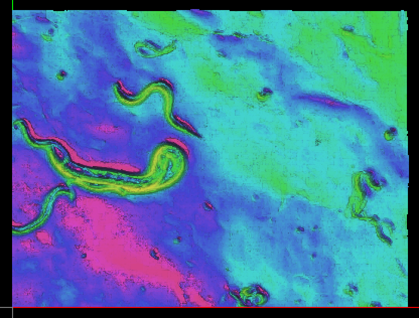
| | 67 | No.67 Revision |
OK, now that it's decided that Bezier surfaces might be good enough, here is a link to the function that needs to be implemented:
http://paulbourke.net/geometry/bezier/
The function is:
I’ve implemented the function. When the number of control points spirals upward, so does the amount of computation and variable precision needed. Loading a 1024x1024 image would be only for the very patient. I had to use the Boost multi precision library, with 100 digits, because long long unsigned int and long double were not big enough. If you find that this answer is suitable, please mark it as correct (click on the checkmark).
The code is at:
https://github.com/sjhalayka/bezier_surface
Below is a screenshot of the curved surface with 64x48 control points, spacer = 0.01. It took roughly an hour to generate on my desktop computer. The colouring uses OpenGL lighting in combination with vertex intensity (which is related to the z value). It's very much like displacement mapping.
The next step is to create a NURBS surface, which is like a Bézier surface, but with a knot vector... whatever that means.
If you are ultimately disappointed in the lack of ability to use large images as Bezier or NURBS control points due to time constraints (literally, days and months of processing time), then you could always try the linear version, which has no problem handling large images.
https://github.com/sjhalayka/linear_surface
A screenshot of the linear surface with 512x384 "control points" is given below. Ultimately, the linear surface is feasible, where the curved surface is not. It took roughly 5 seconds to generate on my desktop computer. This is because it uses only local data to generate the local triangles, where in the case of Bezier or NURBS surfaces, the entire global data is used to generate the local triangles.
Pictured below is a colouring system where hue is related to z depth. Note the yellow-green valleys, and purple-blue mountains:
| | 68 | No.68 Revision |
OK, now that it's decided that Bezier surfaces might be good enough, here is a link to the function that needs to be implemented:
http://paulbourke.net/geometry/bezier/
The function is:
I’ve implemented the function. When the number of control points spirals upward, so does the amount of computation and variable precision needed. Loading a 1024x1024 image would be only for the very patient. I had to use the Boost multi precision library, with 100 digits, because long long unsigned int and long double were not big enough. If you find that this answer is suitable, please mark it as correct (click on the checkmark).
The code is at:
https://github.com/sjhalayka/bezier_surface
Below is a screenshot of the curved surface with 64x48 control points, spacer = 0.01. It took roughly an hour to generate on my desktop computer. The colouring uses OpenGL lighting in combination with vertex intensity (which is related to the z value). It's very much like displacement mapping.
The next step is to create a NURBS surface, which is like a Bézier surface, but with a knot vector... whatever that means.
If you are ultimately disappointed in the lack of ability to use large images as Bezier or NURBS control points due to time constraints (literally, days and months of processing time), then you could always try the linear version, which has no problem handling large images.
https://github.com/sjhalayka/linear_surface
A screenshot of the linear surface with 512x384 "control points" is given below. Ultimately, the linear surface is feasible, where the curved surface is not. It took roughly 5 seconds to generate on my desktop computer. This is because it uses only local data to generate the local triangles, where in the case of Bezier or NURBS surfaces, the entire global data is used to generate the local triangles.
Perhaps a rainbow colouring algorithm based on z depth would help visualize linear surface. Below is a screenshot of the linear surface where yellow-green makes up the valleys, and indigo-violet makes up the mountains.
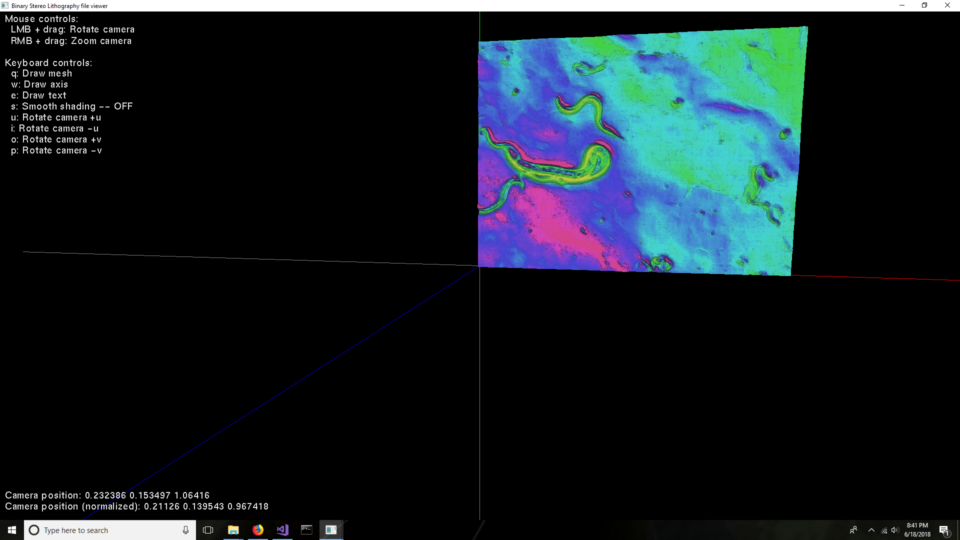
| | 69 | No.69 Revision |
OK, now that it's decided that Bezier surfaces might be good enough, here is a link to the function that needs to be implemented:
http://paulbourke.net/geometry/bezier/
The function is:
I’ve implemented the function. When the number of control points spirals upward, so does the amount of computation and variable precision needed. Loading a 1024x1024 image would be only for the very patient. I had to use the Boost multi precision library, with 100 digits, because long long unsigned int and long double were not big enough. If you find that this answer is suitable, please mark it as correct (click on the checkmark).
The code is at:
https://github.com/sjhalayka/bezier_surface
Below is a screenshot of the curved surface with 64x48 control points, spacer = 0.01. It took roughly an hour to generate on my desktop computer. The colouring uses OpenGL lighting in combination with vertex intensity (which is related to the z value). It's very much like displacement mapping.
The next step is to create a NURBS surface, which is like a Bézier surface, but with a knot vector... whatever that means.
If you are ultimately disappointed in the lack of ability to use large images as Bezier or NURBS control points due to time constraints (literally, days and months of processing time), then you could always try the linear version, which has no problem handling large images.
https://github.com/sjhalayka/linear_surface
A screenshot of the linear surface with 512x384 "control points" is given below. Ultimately, the linear surface is feasible, where the curved surface is not. It took roughly 5 seconds to generate on my desktop computer. This is because it uses only local data to generate the local triangles, where in the case of Bezier or NURBS surfaces, the entire global data is used to generate the local triangles.
Perhaps a rainbow colouring algorithm based on z depth would help visualize the linear surface. Below is a screenshot of the linear surface where yellow-green makes up the valleys, and indigo-violet makes up the mountains.
| | 70 | No.70 Revision |
OK, now that it's decided that Bezier surfaces might be good enough, here is a link to the function that needs to be implemented:
http://paulbourke.net/geometry/bezier/
The function is:
I’ve implemented the function. When the number of control points spirals upward, so does the amount of computation and variable precision needed. Loading a 1024x1024 image would be only for the very patient. I had to use the Boost multi precision library, with 100 digits, because long long unsigned int and long double were not big enough. If you find that this answer is suitable, please mark it as correct (click on the checkmark).
The code is at:
https://github.com/sjhalayka/bezier_surfacehttps://github.com/sjhalayka/bezier_to_mat
Below is It takes a screenshot of small image and enlarges it using a Bezier surface as the curved surface with 64x48 control points, spacer = 0.01. It took roughly an hour to generate on my desktop computer. The colouring uses OpenGL lighting in combination with vertex intensity (which is related to the z value). It's very much like displacement mapping.interpolation method.
The next step is to create a NURBS surface, which is like a Bézier surface, but with a knot vector... whatever that means.
If you are ultimately disappointed in the lack of ability to use large images as Bezier or NURBS control points due to time constraints (literally, days and months of processing time), then you could always try the linear version, which has no problem handling large images.
https://github.com/sjhalayka/linear_surface
A screenshot of the linear surface with 512x384 "control points" is given below. Ultimately, the linear surface is feasible, where the curved surface is not. It took roughly 5 seconds to generate on my desktop computer. This is because it uses only local data to generate the local triangles, where in the case of Bezier or NURBS surfaces, the entire global data is used to generate the local triangles.
Perhaps a rainbow colouring algorithm based on z depth would help visualize the linear surface. Below is a screenshot of the linear surface where yellow-green makes up the valleys, and indigo-violet makes up the mountains.
| | 71 | No.71 Revision |
OK, now that it's decided that Bezier surfaces might be good enough, here is a link to the function that needs to be implemented:
http://paulbourke.net/geometry/bezier/
The function is:
I’ve implemented the function. When the number of control points spirals upward, so does the amount of computation and variable precision needed. Loading a 1024x1024 image would be only for the very patient. I had to use the Boost multi precision library, with 100 digits, because long long unsigned int and long double were not big enough. If you find that this answer is suitable, please mark it as correct (click on the checkmark).
The code is at:
https://github.com/sjhalayka/bezier_to_mat
It takes a small image and enlarges it using a Bezier surface as the interpolation method.method. The result is a blurry mess.
| | 72 | No.72 Revision |
OK, now that it's decided that Bezier surfaces might be good enough, here is a link to the function that needs to be implemented:
http://paulbourke.net/geometry/bezier/
The function is:
I’ve implemented the function. When the number of control points spirals upward, so does the amount of computation and variable precision needed. Loading a 1024x1024 image would be only for the very patient. I had to use the Boost multi precision library, with 100 digits, because long long unsigned int and long double were not big enough. If you find that this answer is suitable, please mark it as correct (click on the checkmark).
The code is at:
https://github.com/sjhalayka/bezier_to_mat
It takes a small image and enlarges it using a Bezier surface as the interpolation method. The result is a blurry mess.mess. For instance, the input is 64 x 48:

And the output is 64x64:

| | 73 | No.73 Revision |
OK, now that it's decided that Bezier surfaces might be good enough, here is a link to the function that needs to be implemented:
http://paulbourke.net/geometry/bezier/
The function is:
I’ve implemented the function. When the number of control points spirals upward, so does the amount of computation and variable precision needed. Loading a 1024x1024 image would be only for the very patient. I had to use the Boost multi precision library, with 100 digits, because long long unsigned int and long double were not big enough. If you find that this answer is suitable, please mark it as correct (click on the checkmark).
The code is at:
https://github.com/sjhalayka/bezier_to_mat
It takes a small image and enlarges it using a Bezier surface as the interpolation method. The result is a blurry mess. For instance, the input is 64 x 48:
48:
And the output is 64x64:
64x64:
| | 74 | No.74 Revision |
OK, now that it's decided that Bezier surfaces might be good enough, here is a link to the function that needs to be implemented:
http://paulbourke.net/geometry/bezier/
The function is:
I’ve implemented the function. When the number of control points spirals upward, so does the amount of computation and variable precision needed. Loading a 1024x1024 image would be only for the very patient. I had to use the Boost multi precision library, with 100 digits, because long long unsigned int and long double were not big enough. If you find that this answer is suitable, please mark it as correct (click on the checkmark).
The code is at:
https://github.com/sjhalayka/bezier_to_mat
It takes a small image and enlarges it using a Bezier surface as the interpolation method. The result is a blurry mess. For instance, the input is 64 x 48:
And the output is 64x64:
You see the main problem now, eh?
| | 75 | No.75 Revision |
OK, now that it's decided that Bezier surfaces might be good enough, here is a link to the function that needs to be implemented:
http://paulbourke.net/geometry/bezier/
The function is:
I’ve implemented the function. When the number of control points spirals upward, so does the amount of computation and variable precision needed. Loading a 1024x1024 image would be only for the very patient. I had to use the Boost multi precision library, with 100 digits, because long long unsigned int and long double were not big enough. If you find that this answer is suitable, please mark it as correct (click on the checkmark).
The code is at:
https://github.com/sjhalayka/bezier_to_mat
It takes a small image and enlarges it using a Bezier surface as the interpolation method. The result is a blurry mess. For instance, the input is 64 x 48:
And the output is 64x64:128x96:
You see the main problem now, eh?
| | 76 | No.76 Revision |
OK, now that it's decided that Bezier surfaces might be good enough, here is a link to the function that needs to be implemented:
http://paulbourke.net/geometry/bezier/
The function is:
The function leads to curved surfaces:
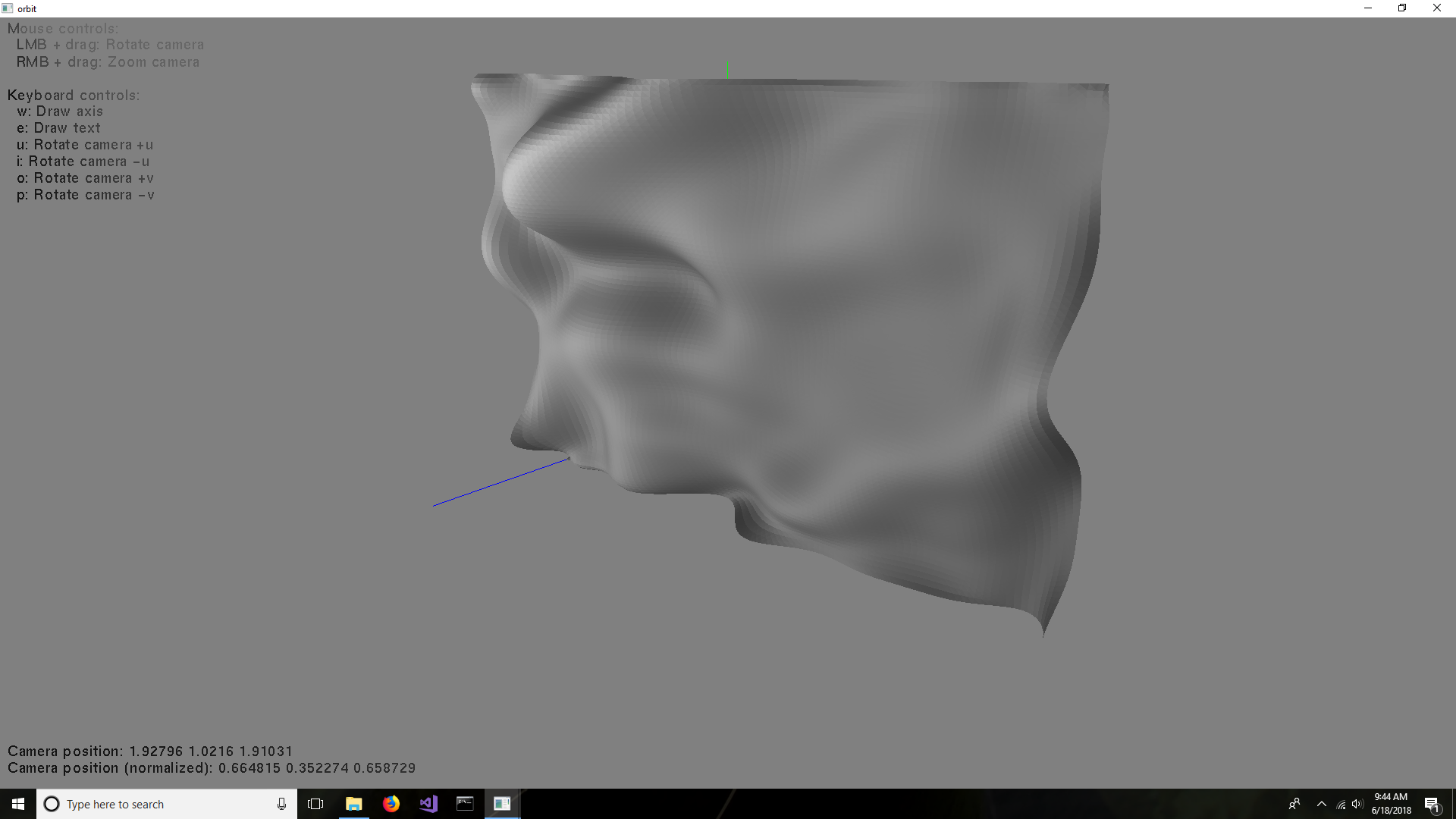
I’ve implemented the function. When the number of control points spirals upward, so does the amount of computation and variable precision needed. Loading a 1024x1024 image would be only for the very patient. I had to use the Boost multi precision library, with 100 digits, because long long unsigned int and long double were not big enough. If you find that this answer is suitable, please mark it as correct (click on the checkmark).
The code is at:
https://github.com/sjhalayka/bezier_to_mat
It takes a small image and enlarges it using a Bezier surface as the interpolation method. The result is a blurry mess. For instance, the input is 64 x 48:
And the output is 128x96:
You see the main problem now, eh?
| | 77 | No.77 Revision |
OK, now that it's decided that Bezier surfaces might be good enough, here is a link to the function that needs to be implemented:
http://paulbourke.net/geometry/bezier/
The function is:
The function leads to curved surfaces:
I’ve implemented the function. When the number of control points spirals upward, so does the amount of computation and variable precision needed. Loading a 1024x1024 image would be only for the very patient. I had to use the Boost multi precision library, with 100 digits, because long long unsigned int and long double were not big enough. If you find that this answer is suitable, please mark it as correct (click on the checkmark).
The code is at:
https://github.com/sjhalayka/bezier_to_mat
It takes a small image and enlarges it using a Bezier surface as the interpolation method. The result is a blurry mess. For instance, the input is 64 x 48:
And the output is 128x96:
You see the main problem now, eh?
| | 78 | No.78 Revision |
OK, now that it's decided that Bezier surfaces might be good enough, here is a link to the function that needs to be implemented:
http://paulbourke.net/geometry/bezier/
The function is:
The function leads to 2D curved surfaces:surfaces in 3D space:
I’ve implemented the function. When the number of control points spirals upward, so does the amount of computation and variable precision needed. Loading a 1024x1024 image would be only for the very patient. I had to use the Boost multi precision library, with 100 digits, because long long unsigned int and long double were not big enough. If you find that this answer is suitable, please mark it as correct (click on the checkmark).
The code is at:
https://github.com/sjhalayka/bezier_to_mat
It takes a small image and enlarges it using a Bezier surface as the interpolation method. The result is a blurry mess. For instance, the input is 64 x 48:
And the output is 128x96:
You see the main problem now, eh? It's too smooth.
| | 79 | No.79 Revision |
OK, now that it's decided that Bezier surfaces might be good enough, here is a link to the function that needs to be implemented:
http://paulbourke.net/geometry/bezier/
The function is:
The function leads to 2D curved surfaces in 3D space:
I’ve implemented the function. When the number of control points spirals upward, so does the amount of computation and variable precision needed. Loading a 1024x1024 image would be only for the very patient. I had to use the Boost multi precision library, with 100 digits, because long long unsigned int and long double were not big enough. If you find that this answer is suitable, please mark it as correct (click on the checkmark).
The code is at:
https://github.com/sjhalayka/bezier_to_mat
It takes a small image and enlarges it using a Bezier surface as the interpolation method. The result is a blurry mess. For instance, the input is 64 x 48:
And the output is 128x96:
You see the main problem now, eh? It's too smooth.
| | 80 | No.80 Revision |
OK, now that it's decided that Bezier surfaces might be good enough, here is a link to the function that needs to be implemented:
http://paulbourke.net/geometry/bezier/
The function is:
The function leads to 2D curved surfaces in 3D space:
I’ve implemented the function. When the number of control points spirals upward, so does the amount of computation and variable precision needed. Loading a 1024x1024 image would be only for the very patient. I had to use the Boost multi precision library, with 100 digits, because long long unsigned int and long double were not big enough. If you find that this answer is suitable, please mark it as correct (click on the checkmark).
The code is at:
https://github.com/sjhalayka/bezier_to_mat
It takes a small image and enlarges it using a Bezier surface as the interpolation method. The result is a blurry mess. For instance, the input is 64 512 x 48:
384:
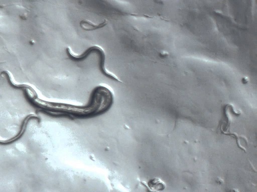
And the output is 128x96:
64x64:

You see the main problem now, eh? It's still too smooth...
| | 81 | No.81 Revision |
OK, now that it's decided that Bezier surfaces might be good enough, here is a link to the function that needs to be implemented:
http://paulbourke.net/geometry/bezier/
The function is:
The function leads to 2D curved surfaces in 3D space:
I’ve implemented the function. When the number of control points spirals upward, so does the amount of computation and variable precision needed. Loading a 1024x1024 image would be only for the very patient. I had to use the Boost multi precision library, with 100 digits, because long long unsigned int and long double were not big enough. If you find that this answer is suitable, please mark it as correct (click on the checkmark).
The code is at:
https://github.com/sjhalayka/bezier_to_mat
It takes a small image and enlarges it using a Bezier surface as the interpolation method. The result is a blurry mess. For instance, the input is 512 x 384:
And the output is 64x64:
You see the main problem now, eh? It's still too smooth?
