This forum is disabled, please visit https://forum.opencv.org
| 2020-03-28 07:19:35 -0600 | received badge | ● Notable Question (source) |
| 2017-09-10 16:45:23 -0600 | received badge | ● Nice Answer (source) |
| 2017-05-01 08:00:47 -0600 | received badge | ● Popular Question (source) |
| 2013-09-09 06:37:06 -0600 | answered a question | findchessboardCorners result I don't know if I understand your question correctly...but: The size "board" you set as the parameter for findChessboardCorners does not correspond to the squares but to the inner corner points. So if you want to cover 3 x 3 squares you need to set the size to (4,4) - you will then find 4 inner corner points made up by 5 squares. |
| 2013-09-07 05:33:33 -0600 | commented question | rules for generating calibration pattern you're right, I updated the question - but my main intention is to understand the rules not to solve the error of the python script |
| 2013-09-07 04:23:14 -0600 | commented question | rules for generating calibration pattern "It stops without an error message" |
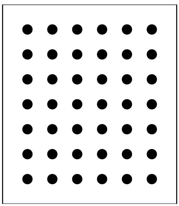
| 2013-09-07 03:54:30 -0600 | asked a question | rules for generating calibration pattern Hi all! We need a calibration pattern with outer dimensions of around 600 mm x 600 mm. I tried to use the python script which can be found in the doc folder of the OpenCV distribution but it does not generate an svg of this size. It stops without an error message and does not write an svg file. So I want to create the pattern on my own and want to understand the "rules" (and I want to understand them not only because the python script is not working for my size):
Because I can not print a pattern of this size and have to pay for the printing, I need to know the rules and can not try many different things. Here is a sample pattern generated by the python script (I guess you could resize it to the required final size), I only added a bounding rect manually. The command line: So I use a square size of 50 and the script automatically sets the radius of the circles to 1/5 of this size => 10. This is hard-coded and there is a comment in the script: "#radius is a 5th of the spacing TODO parameterize" Obviously this is adjustable. So, this is one of my questions: which is the perfect balance between spacing and radius?
Thanks! |
| 2013-09-07 03:20:40 -0600 | commented question | type and size of calibration pattern for most accurate results And did they mention which relative size the pattern should have in the final image? I guess if it's too small the calibration is only valid for small parts of the image and not for the whole covered area? |
| 2013-09-07 03:18:45 -0600 | commented question | building photoshop-style black-white-conversion I already loop through all the pixels and apply a custom grayscale conversion (http://answers.opencv.org/question/12947/custom-grayscale-conversion/) but I want to understand how the weight for R, G and B can be calculated depending on the setting in Photoshop. How to they correspond? |
| 2013-08-25 09:59:48 -0600 | asked a question | building photoshop-style black-white-conversion Hi all! I'm trying to separate some coloured object from my background. Before starting with OpenCV I'm using a test image in Photoshop to check which color channels or which combination of color channels are the best. |
| 2013-08-25 08:59:10 -0600 | asked a question | type and size of calibration pattern for most accurate results Hi! I want to use OpenCV for accurate measuring - so the first step should be the best camera calibration possible.
Does anyone have some experience which type is the most accurate? Another important parameter is the relative size of the pattern in the camera image.
Are there any rules for the minimum size? For example the pattern should cover 25% of the image or something like that? Thanks! |
| 2013-05-14 12:21:41 -0600 | received badge | ● Teacher (source) |
| 2013-05-06 11:16:59 -0600 | received badge | ● Scholar (source) |
| 2013-05-06 04:59:52 -0600 | asked a question | custom grayscale conversion I'm trying to improve my edge detection and found out, what is logical: some edges are detected better in the red channel, others in the green etc. I would like to use only one Canny-call and not three on each channel. When I use BGR2GRAY the mixture of the channels is not optimal for my camera live image. Is it possible to change the weight of each channel during the conversion? Or is there any known custom algorithm for this? Thanks! |
| 2013-05-06 01:49:38 -0600 | answered a question | opencv/findContour crashes, v2.4.4, MS visual studio 2010. edit:damaged head. Here is some code for using findContours: You should try to make this work, because findContours is an elementary function which you will use often. |
| 2013-05-06 01:29:50 -0600 | commented answer | Can't set resolution of video capture Sorry, this is only working on Windows...you are using Linux as I realised now... |
| 2013-05-06 01:27:20 -0600 | answered a question | Can't set resolution of video capture I also had some problems with my logitech webcam and OpenCV capturing. I then used the videoInput Library and could set everything I needed. Give it a try! |
| 2013-05-05 06:11:34 -0600 | received badge | ● Supporter (source) |
| 2013-05-04 14:51:12 -0600 | answered a question | opencv/findContour crashes, v2.4.4, MS visual studio 2010. edit:damaged head. Try to use a new variable of the type Mat as result of your threshold call, looks like test (which is a clone of m) is not a binary image |
| 2013-05-04 14:28:00 -0600 | received badge | ● Student (source) |
| 2013-05-04 13:18:09 -0600 | asked a question | measuring distance between two balls in millimeters - how to improve accuracy Hi! I'm currently learning OpenCV and my current task is to measure the distance between two balls which are lying on a plate. My next step is to compare several cameras and resolutions to get a feeling how important resolution, noise, distortion etc. is and how heavy these parameters affect the accuracy. If the community is interested in the results I'm happy to share the results when they are ready! The camera is placed above the plate using a wide-angle lens. The width and height of the plate (1500 x 700 mm) and the radius of the balls (40 mm) are known. My steps so far:
The results: an error of around 4 mm at a distance of 300 mm, an error of around 25 mm at a distance of 1000 mm But if I measure are rectangle which is printed on the plate the error is smaller than 0.2 mm, so I guess the calibration and undistortion is working good. I thought about this and figured out three possible reasons:
I hope someone can help me to improve this and I hope this topic is interesting for other OpenCV-starters. Thanks and best regards! |
| 2013-05-03 02:20:04 -0600 | answered a question | Does the canny method apply Gaussian Blur? I'm pretty sure that canny() does not apply any blur to the image. You have to do it before calling canny(). Take a look at bilateralFilter as an alternative to GaussianBlur - it keeps the edges sharper. |
| 2013-05-02 07:01:56 -0600 | received badge | ● Editor (source) |
| 2013-05-02 06:44:45 -0600 | asked a question | calculate 3d pose of sphere based on 2d ellipse Hello all, at the moment I'm using OpenCV to detect balls in an image by finding the 2d ellipse of the balls. I now need to find out the exact position of the ball in world coordinates - I know the radius of the balls. If the ball is lying close to the optical center of the camera then the position is quite accurate - but if the ball moves to the borders of the image, the position has a growing error, because of the perspective distortion of the camera - the ball is seen from the side for example. I read several papers about this problem and there seems to be a solution (http://www.mie.utoronto.ca/labs/ciml/projects/rob_vision/Tony.pdf on page 4) but I'm not sure how to implement this. My current idea: Has anyone some expirience with this? I hope someone can point me in the right direction. Thanks a lot! |