This forum is disabled, please visit https://forum.opencv.org
| 2017-08-04 11:17:47 -0600 | asked a question | Projection matrices in OpenCV vs Multiple View Geometry I am trying to follow "Multiple View Geometry in Computer Vision" formula 13.2 for computing the homography between for a calibrated stereo rig. It should be simple math H = K' (R - t. transpose(n) / d) inv(K) Where H is the 3x3 homography. K and K' are 3x3 camera intrinsic matrices, R is a 3x3 rotation between the cameras. t is column vector translation between the cameras. n is a plane normal vector and d is the constant of the plane equation of a plane that both cameras are viewing. The idea here is that going right to left, a homogenous pixel coordinate is unprojected to a ray, the ray is intersected with a plane and the intersection point is projected to the other image. When I plug numbers in and try to match up two captured images I can't get the math as shown to work. My main problem is that I don't understand how simply multiplying a 3D point by a camera matrix K can project the point. In the opencv documentation for the calibration module: x' = x / z y' = y / z u = fx * x' + cx v = fy * y' + cy By the above math, x and y are divided by z before the focal length is multiplied. But I don't see how the math from the text accomplishes the same thing by merely multiplying a point by K. Where is the divide by z in the formula for H? Can someone help with this problem that is probably just notation? Scott |
| 2017-03-21 17:15:05 -0600 | received badge | ● Supporter (source) |
| 2017-01-26 13:36:24 -0600 | asked a question | Aruco corner refinement poses are unstable in OpenCV 3.2 I am using a moving camera and a fixed Aruco marker. The 3D pose results I get even as the camera is pretty still vary greatly per frame which is why I claim they are unstable. I determined that the problem goes away when I turn off corner refinement in the Detector Parameters. So my question is whether there is anyone who knows that stuff well enough to fix it or if it is user error. I have sample code and images that demonstrate one answer with corner refinement and another very different answer without corner refinement. FYI: we kept the corner refinement defaults because we didn't understand them and only turned on the feature. If this is just our luck for not understanding the feature then I can live with that. My current work around is to just turn it off. I tried to post two sample pictures that demonstrate a good answer and a bad answer but the system said I don't have enough points. Scott |
| 2016-10-21 07:25:35 -0600 | received badge | ● Editor (source) |
| 2016-10-20 17:20:03 -0600 | answered a question | Radial distortion parameter k2=-300, is it possible?
I just had this problem today and asked myself the same question. If you look at the math you find that the radial distortion is (just showing x component) where r^2 = x^2 + y^2 is: x' = x( 1 + k1 r^2 + k2 r^4 + k3 r^6) I originally thought that x was in pixels and therefore if x were merely 10 pixels from center then the r^6 term would dominate no matter what the other terms. But looking through the math more closely ,x = X/Z and is not in pixels. It is dimensionless. In fact I can imagine that with most cameras with a FOV less than 90 degrees, that Z will be greater than X so X/Z will be less than one and y=Y/Z will be less than one. Now when you use those fractions as inputs to the distortion formulas you get much more reasonable results. The higher order terms are now less dominant than more dominant and it makes more sense. In other words, r^2 = (X/Z)^2 + (Y/Z)^2 where X, Y, and Z are the 3D camera space coordinates. This may not help your overall problem with your cameras and this question is very old so you've probably moved on but I hoped to answer your specific question. |
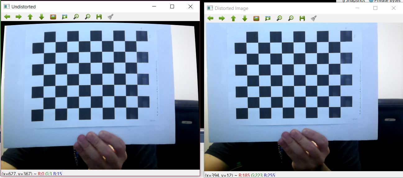
| 2016-10-20 15:51:29 -0600 | asked a question | Original Image from webcam is undistorted. Undistort actually distorts. My friend and I are doing a sample camera calibration using the webcam on his Alienware laptop. We cannot understand why the original image is undistorted and we get a distorted image when we call undistort with the camera intrinsics. The attached picture shows that the results are backwards from expectations. When he first showed this to me I laughed at him and said he just switched the images by mistake. If so, I can't find how he did it. We used the cpp-example-calibration to get the camera intrinsics: windows> cpp-example-calibration.exe -w=8 -h=6 -pt=chessboard -n=30 -d=2000 -s=0.13 I know that the 8x6 chessboard expressed in the parameters is different than in the picture. We actually used a huge posterboard sized chessboard to do the calibration and we took the pictures with a smaller board that is easier to hold. The side by side pictures are meant to show where distortion exists. They were not a part of calibration. The calibration resulted in this data: %YAML:1.0
calibration_time: "Thu Oct 20 20:25:14 2016"
image_width: 640
image_height: 480
board_width: 8
board_height: 6
square_size: 1.2999999523162842e-01
aspectRatio: 1.
flags: 2
camera_matrix: !!opencv-matrix
rows: 3
cols: 3
dt: d
data: [ 8.4125490263403651e+02, 0., 3.1179038300397195e+02, 0.,
8.4125490263403651e+02, 1.2247027042886921e+02, 0., 0., 1. ]
distortion_coefficients: !!opencv-matrix
rows: 5
cols: 1
dt: d
data: [ 2.4482174065616116e-01, -5.9553709824779455e-01,
-8.4895736453074480e-02, 7.9072223119576700e-03,
1.3055992934480314e+00 ]
avg_reprojection_error: 8.5143610263133207e-01
Then we used this code to capture one frame of data from the camera and show the original capture and the results of applying undistort(). The hard-coded values are the cut/pasted camera intrinsics. I expect that if the captured images from the camera have no distortion that the calibration procedure would result in distortion coefficients that are very near zero. That is not what happened. Yet the re-projection error is pretty small indicating a good calibration. What is going on? |
| 2015-08-10 00:17:47 -0600 | commented question | Input to SolvePNP. Does my program need to match up the points? The manual does say "corresponding" points. The act of writing a post has helped me face this extra step of the work. |
| 2015-08-10 00:17:47 -0600 | asked a question | Input to SolvePNP. Does my program need to match up the points? I am trying to get SolvePnP to work with a simple example but it is giving me very unstable results across frames when I track a nonplanar 3 point constellation. Is it my program's job to provide correspondence between the 2D points and the 3D points? In other words do I have to provide SolvePnP with a 2D list and a 3D list where the points are already known to match up? Thanks in advance Scott |