This forum is disabled, please visit https://forum.opencv.org
| 2015-07-15 03:53:42 -0600 | commented answer | feature matching video stream? Hi. I'm sorry for the late answer ! I'm quite overwhelmed these months. For sure I would like to share it, I would need to strip out some libraries which I attached, that we use in my research group, and replace with a simple version of it. Still, I'm not sure if you would be able to compile it in a non-Linux platform, and surely making it compile in Visual Studio would be a feat. The thing is tangled with a bunch of boost mutexes and shared pointers... |
| 2015-06-24 09:17:37 -0600 | commented answer | feature matching video stream? Sadly a lot of good algorithms have a ROS dependency tacked on. ..It is a pain to port such algorithms (I did remove recently the ROS dependency of LSD-SLAM, took one week). Anyway, several of such algorithms have dependencies here and there that makes it not worthy to you just add as library into your code as it will be a huge "Frankenstein" code... for example, the PTAMM has a lot of functionality that is present in OpenCV implemented by a bunch of uncommon libs. It takes a long time, but pays off read the papers and if possible the code, and write the thing yourself. I really recommend read the thesis above if you have time. It have a very good explanation how to compute the Motion Estimator. I hope that this helps you in your project |
| 2015-06-23 07:43:25 -0600 | answered a question | feature matching video stream? I believe, from your posts that you are trying to implement a sort of SLAM solution. This is not an easy task, and I recommend you to read the works of LSD-SLAM (semi-dense approach), and PTAMM (feature-based approach) to have an idea of two very robust (albeit distinct) solutions. Regarding this particular issue: Determining the camera pose by feature-matching is extremely jittery. A small amount of camera noise can make a calibration feature "disappear" and affect the solvePNP. This is even aggravated if you are using RANSAC. Keep in mind that RANSAC is non-deterministic algorithm. It will find the solution with least error from a a subset of your input. This means that if a small group of features with a certain error provides a solution with small error (but wrong because their positions are contaminated with noise), your camera pose will "jump". I fast solution that come to my mind is perform some feature matching and then pass the estimated position of the features as initial guess of an optical flow algorithm. Note that optical flow algorithms are not robust to occlusion, so you will need to make a further check if the tracker feature matches with the original one. Then you can use the input to solvePNP. A better yet solution would use a weighted motion estimator instead solvePNP, so features with low confidence would affect the camera calibration less than properly matched points, but keeping all the information into account. This isn`t implemented in OpenCV, but there is a complete description in a the thesis "Visual Tracking for Augmented Reality" from Georg Klein (Univ. of Cambridge), about how to implement one. I hope that this helps. |
| 2015-06-23 04:33:12 -0600 | commented question | solvePnP camera coordinates. If you are using the camera centre as origin, it means that you are using the coordinates in camera space instead world space. You wont be able to compute the motion of the camera in this way. Since you NEED a reference, set the world coordinate space as the camera pose of the first triangulation. Now you should compute the camera pose and rotation relative to the camera pose of this first triangulation. It means that after every triangulation, you must convert such triangulated points to world space coordinates. For this, just use the matrix T = E^(-1) (that is the inverse of the camera extrinsic matrix given my solvePnp) to transform every triangulated point. Note that transforming the point (0,0,0) by T will give you the camera centre in world coordinates. |
| 2015-06-23 04:27:35 -0600 | commented question | Surf Giving Weird Keypoints Well, the feature will match with such background and the fork, so if you change the background that feature wont be present at all. Of course, there is the possibility of false matching, but this happens even with features found within the fork. At first, you should not match directly a feature with the closest feature found in the image, rather do a more robust comparison do eliminate ambiguous matches (check this book here : http://szeliski.org/Book/ , it is very helpfull) |
| 2015-06-22 05:17:58 -0600 | commented question | Surf Giving Weird Keypoints FAST is a corner detector for tracking, so it is natural that it will find only corners. SURF, for another side detects regions that are identifiable in several scales, such that it can be relatively scale independent for feature matching. You will be able to see that if you draw the circles according the size attribute of cv::Keypoint. |
| 2015-06-22 03:18:31 -0600 | commented question | solvePnP camera coordinates. Well, solvePNPRansac is quite robust, if you give enough iterations. So your problem is somehow in your input data or how you are processing it: 1) You must be aware that the input and output matrices (camera matrix,, rvec,tvec) are type CV_64F (64 bit float), so not try to read their values using float in the typecasting. 2) You triangulation method is not giving you good results. If your 3d points aren't good, solvePNP wont give you a good movement. Additionally, 3d points should be in metres and in world coordinates. 3)The tracking method is giving you some improper results, so that the 2d input points are wrong. 4) The matching between 2d and 3d points passed as input is somehow wrong. Each i-th element on the 2d vector corresponds to i-th element in the 3d vector. They MUST match. |
| 2015-06-17 15:30:52 -0600 | received badge | ● Nice Answer (source) |
| 2015-06-17 06:20:28 -0600 | received badge | ● Nice Answer (source) |
| 2015-06-17 03:59:13 -0600 | answered a question | solvePnp object - to - camera pose. The function solvePnp (or solvePnPRansac) consider that the 3D points given are in absolute world coordinates, thus it will return a rotation and translation matrix of the extrinsic matrix of the camera. That is, a matrix that will convert 3D world coordinates to 3D coordinates relative to the camera centre. If you compute the inverse of said matrix, you will have the camera transform matrix, which will state the camera rotation and translation in relation to the "world". Note that the rotation is given in Euler angles, so you will need use cv::Rodrigues to convert it to a 3x3 rotation matrix. The extrinsic matrix is then a 4x4 matrix in the form you can just use cv::Mat::inv() to compute the inverse. |
| 2015-06-16 11:34:36 -0600 | answered a question | Feature matching 2d to 3d points. The match procedure of the BFMatcher class will take two inputs, queryDescriptors and trainDescriptors, which are arrays of descriptors (normally each line of a cv::Mat object corresponds to a individual descriptor), and return a std::vector object of type cv::DMatch. Each element of this output array corresponds to the correlation of a matched query descriptor to a train descriptor. So matches[i] has tree important attributes: trainIdx, queryIdx and distance. This element states that the line queryIdx of queryDescriptors matches with the line trainIdx of trainDescriptors with distance distance. Well, after matching you can assemble the inputs of solvePnp (which are : array of 2d positions, an array with the corresponding 3d positions) using those indexes. This depends if the 3D positions are from the query or train descriptors. If you know the 3d positions of the train descriptors, you will use the 2d positions of the matched query descriptors and then compute the camera pose of the query image with this matching data. Normally you use the distance attribute to filter bad matches. I hope that this helps. |
| 2015-06-16 11:18:26 -0600 | answered a question | Large Integer in cv::Mat Truncating will occur if you use a cv::Mat object of type CV_8U (or its variants CV_8UC1, etc...) and try to write an value larger than 255. Create a cv::Mat object of a larger signed type, for example CV_32S or CV_32U instead CV_8U. CV_32S will use 32bit integer type. The assignment of values can be done in the following way: It is VERY important to you know the type of your matrix before assigning a value. If you try to assign a large integer value using "at.< int32_t >" in a matrix of type CV_8U, your program is very likely to crash at certain point, since OpenCV don't verify this and will write outside the allocated memory boundaries...or worse, invading a memory block of another allocated data structure of your software. ALWAYS check the type of your matrix with the cv::Mat::type() function. Another thing: cv::imshow seems to not like any matrices that arent of type CV_8U and CV_32F. Use cv::Mat::convertTo to convert the matrix to a compatible type for displaying and scale its values. |
| 2015-06-11 04:42:28 -0600 | answered a question | resize kinect color stream to match depth. Well, I'm never worked with Kinect 2, but I suppose that it is very similar to the original Kinect. The fact is that the Kinect has 2 cameras (one IR and another RGB), and it generates it depth map by projecting a pattern over the scene using a IR projector and computing the depths by using the input of the IR camera. That said, the raw data from the RGB camera wont be aligned with the depth data because the cameras are distinct. It is not a mere matter of just resizing the images. The depth map has to be properly mapped , or better yet, registrated. This means that you have to re-project the depth points into the RGB camera point of view and assign the color As I said, I'm not sure how you capture the data from the Kinect 2. If you are using the OpenNI backend of OpenCV, you can do just as I explained in this another question HERE, and the depth map will be properly registered with the RGB image. If the way that you are extracting this data from the Kinect is not this, you must determine the camera pose of the RGB camera relative to the IR camera pose to do the reprojection. Calibrating the cameras (only once !): Calibrate both cameras as a stereo pair, using cv::stereoCalibrate with the camera matrices that you computed in the previous step and a calibration pattern viewed by the same cameras. You will obtain the rotation, translation needed to re-project the points. If you have the camera matrices of the RGB and IR camera a priori, it will be much better. The ones from Kinetic 1 are quite well known and can be found in internet. I believe that it is simple to find the ones from Kinetic 2 at this point... Colouring the depth map (for every frame): With the procedure above, you have the rotation and translation matrices and the camera matrix of the RGB camera. All that you have to do is project the 3D depth point into the RGB camera space using cv::projectPoints, and assign the colour of the pixel (or interpolation of the nearby pixels). Note that some points will be colourless since they aren't visible by the RGB camera. |
| 2015-06-09 07:24:55 -0600 | commented question | OpenCV Crash when processing in paralelle OpenCV works very well in parallel processing, except with anything related to GUI management ... are you calling "cv::imshow" and "cv::waitKey" in multiple threads ? If so, you should refrain to use such functions in only one thread. |
| 2015-06-09 02:43:07 -0600 | commented question | markers detection Depends on how much the markers will rotate or change the appearance, but multi-scale template matching or feature matching (finely tuned) should work much better than classifiers. |
| 2015-06-05 03:26:12 -0600 | commented question | VideoWriter produces empty wmv I noticed that in Windows my output videos would be of size 0 when I didn't had the codec or even using some options from the codec settings. There is not such problem when a codec pack is installed, thought. |
| 2015-06-01 02:21:39 -0600 | commented answer | Kinect RGB and depth frame I have edited the answer in order to clarify better your doubts. |
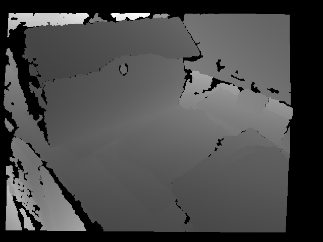
| 2015-05-29 04:31:49 -0600 | answered a question | Kinect RGB and depth frame The registered depth data is given in a cv::Mat structure with data in several types. If you retrieve it by using CV_CAP_OPENNI_DEPTH_MAP or CV_CAP_OPENNI_POINT_CLOUD_MAP, this matrix will be respectively of CV_16UC1 or CV_32FC3. The first is a 16-bit integer with the depth in millimetres, and the second each element will be an X,Y,Z vector of the relative 3D position of the point to the camera in metres . You can easily access the data by accessing the individual elements of the Mat object. see the example: I hope that it helps. About the alignment of the images: The flags sent in the "set" command to the "VideoCapture " structure in the example above (more specifically "CV_CAP_OPENNI_DEPTH_GENERATOR_REGISTRATION") ensure that the RGB and the depth frame will be properly registered/aligned by the OpenNI backend. As side effect of the registration, there will be a black border around the scene which corresponds to regions where the field of view of the IR sensor does not overlap with the RGB sensor. See the example bellow. As you can see, there is a surrounding area where there isn't any depth information (the black regions):
|
| 2015-04-16 06:31:41 -0600 | commented question | Visual Vocabulary Tree As far I cannot disclose the code directly (there is some IP over its library), I would be more than happy to aid in write a OpenCV module which implements a Vocabulary Tree training, and search with distinct type of descriptors (floating point,binary) and distance functions(l2,l1, hamming). It would be nice to add to at least a basic Inverted File implementation which is used by the Nister´s algorithm and compatible with a BoW approach. I wish that I had more time to write a proper Photometric Stereo module... |
| 2015-04-14 10:17:32 -0600 | commented question | Visual Vocabulary Tree It is not implemented in OpenCV. I wrote this VT algorithm some years ago using OpenCV structures based both in a code that I found long time ago (C++) and in DBOW. Keep in mind that you will need to compute a Vocabulary Tree using a large amount of descriptors and with sufficient variation if you want reasonable results, as tree should be well populated (most of leaves with an assigned descriptor value). It works very well for tracking loss recovery for SLAM algorithms :) |
| 2015-02-17 01:40:41 -0600 | received badge | ● Enthusiast |
| 2015-01-28 04:26:32 -0600 | commented question | Streaming video from Rpi to PC using gstreamer/netcat Interesting ! How much delay you achieve with this set-up ? |
| 2015-01-21 02:04:08 -0600 | commented question | Canny edge detection applying to video, but converted video is not saving I dont known much aboout the Python implementation of OpenCV, as I use only C++. In my experience, in most cases where VideoWriter fails to write any frame silently and generates just the file header is when the width and height of the written frame is not the same as the specified in the VideoWriter constructor. Also, you should verify if Mat type of "edges" is CV_8UC3 (8bit, 3 channel). Sending a CV_32F(float) or a CV_64F(double) frame may cause problems. |
| 2014-11-21 16:06:42 -0600 | commented question | Logitech HD Pro Webcam C920 This is very weird. I use extensively the C920 and C930 with OpenCV in Debian and Windows 7 for Augmented Reality applications using either 848x480 or higher resolutions, without installing anything exceptional (default drivers or Logitech ones). Note that OpenCV 2.4.3 is VERY outdated. You should be using 2.4.9 or 2.4.10. |
| 2014-11-20 05:12:43 -0600 | answered a question | Optic Flow on pairs of images Yes you can perfectly use such algorithms with still images. In fact all that they expect in OpenCV is the previous and the next frame images. So it does not make any differentiation. Of course, you have to take into account that Optical Flow works better when the images differs not much from the previous one. |
| 2014-11-20 02:17:53 -0600 | received badge | ● Citizen Patrol (source) |
| 2014-11-14 04:37:52 -0600 | commented question | modify pixel of image with 0.01 If your image is of type 8UC1 (thats why I suppose that you are using uchar), its values are integers, not floating point, and is very likely that they are between 0(black) and 255(white). The least value that you can add is 1. Attributing 0.01 to a uchar variable will round it to 0. |
| 2014-11-13 08:51:45 -0600 | answered a question | finding icon on taskbar To find an icon with feature matching, it should have enough and distinctive features to be able to be detected. I must say that there are icons that wont be easy to detect with this approach. Since your icon is not rotating or being distorted by perspective/affine projection, template matching seems me the best option for you. OpenCV has the matchTemplate function, which computes a similarity score for every pixel of the image, given a template. There is a good tutorial about this in the Tutorials section in this link. If the icon size varies, you should try a multi-scale approach, that is, try to small templates, and increase its size until find a good detection score. -----------POST-COMMENTARY-------------- Well, sadly I cannot provide you working code for this, but I'll try to explain you the ideia. In fact if you intend to do anything serious in OpenCV, you should familiarize yourself with its basic structures (Point, Mat, Vec...). Indeed, the example provided always detect something, even if it is not the most adequate match. A more robust solution, would be instead get the most likely region, get a set of most likely matches. That is, for the returned matrix "result" in the code of the tutorial, instead get the maximum value of the matrix (CV_TM_CCORR, CV_TM_CCORR_NORMED, CV_TM_CCOEFF, CV_TM_CCOEFF_NORMED) or the minimum value of the matrix (CV_TM_SQDIFF, CV_TM_SQDIFF_NORMED), you should scan the "result" for the N highest/lowest values on the result matrix. You can cut some off of such candidates by using some threshold. This will give you a set of candidates. There is a reasonable way to identify if it is a good match or not. What you can do next is try to compute the photometric parameters for each candidate. Lets, say that this template has its pixel intensities multiplied by constant factor A, and a constant "background" brightness added B in the scene. That is, every pixel of the patch/template T on the scene S will have this form: A(T[x,y]) + B = S[u,v] Where (x,y) is the point of template T mapped to the point (u,v) in S. At first, a good candidate would be the one where A is closest to 1.0 and B closest to 0. Positive values of A and B means a shaded template (A < 1.0 -> darker, A > 1.0 -> brighter), where A and B < 0 are meaningless, thus a false match. Take into consideration that there can be some numerical errors due floating point representation in PCs, so A = 0.9998 and B=-0.01 still means a good match. So, you must find the best value of A and B for each location candidate assembling a linear system using the template and the scene data. Note that, with the data from the images, this is a overdetermined system. Use Linear Least Squares) in order to solve it. OpenCV provides a linear system solver with cv::solve, so you can use ... (more) |
| 2014-11-10 02:28:21 -0600 | answered a question | Pose Estimation and Feature Detection Depends on your application. Do you have a set of fixed markers or a several markers which can move around the scene ? As you said, solvePNP will give the RT matrix of a camera given the 3D coordinates of some points on the image, and these coordinates have to be known by another method. For augmented reality with markers, the concept is that you have an idea about the real-world size of the markers a priori, so, for instance, for a 10cm square marker you can say that the coordinates of its corners are (0,0,0), (0.1,0,0), (0,0.1,0), (0.1,0.1,0). Once you have detected it, solvePNP will give you the relative pose of the camera towards this marker. Note that the RT matrix is the transform that converts absolute world coordinates to relative coordinates towards the camera. So, if the centre of the marker is the position P = (0.05,0.05,0,1.0) (homogeneous coordinates) will be the centre of the marker, and its relative position in relation to the camera will be RT*P. This can be also be used to determine the marker orientation. Likewise, if you want draw something as overlay over the marker (augmented reality), you can use the coordinates of the marker as the "world coordinates", and render the overlay based in the computed camera pose. That said, if you have several mobile markers, you have to compute for each marker the relative pose of the camera from it with separated calls of solvePNP. Note that if the appearance of the markers is known, and you don't have their real-world size, you will have to assign a defined size in an arbitrary unit, since there is a infinite number of possible sizes + 3D positions which will have the same appearance in the camera. Important: RT is a 4x4 Matrix and P is a 4x1 matrix (x,y,z,w) where w is 1.0 (homogeneous coordinates). Solve PNP will give you the the euler angles R', and a translation matrix T'. You should compute the rotation matrix R (3x3) using cv::Rodrigues. I use the following procedure to compute RT from rvec and tvec from solvePNP : Based in your comment, it is very similar with what I had implemented such thing long time ago, using pictures as AR markers. Basically, as pre-processing step, you have first to compute the keypoints and associated descriptors for each AR marker. That is, for a marker, you will have a set of ... (more) |
| 2014-11-05 10:39:36 -0600 | commented answer | Detecting an incoming bus in opencv? I do not think this approach wrong. It is possible to even measure (very roughly) its distance, since it is trivial match the characters with real world coordinates. Like the others it has its own drawbacks. One that bothers me, is that the license plate can be easily occluded by a car/bike/pedestrian ... at least in my city, they are placed quite low. Without know more details, it is hard to tell a good solution. |
| 2014-10-28 10:26:22 -0600 | commented answer | Correct barrel distortion without reference images The "real" OpenCV function is the cv::remap function. All that you have to compute the mapping matrices only once, as initialization, and give it as parameter to the remap function. It will un-distort the frame using any optimization options available in OpenCV. If you read the documentation, you will see that "cv::undistort", for lens distortion removal, uses "remap" internally. |
| 2014-10-28 09:30:42 -0600 | commented question | FlannBasedMatcher correct declaration Maybe the attribution that you doing within the "ifs" is not really copying the data from the temporary matrix which you created, just giving the reference, and the object points to unallocated memory after the "temp" variable is released. Note that type = 0 corresponds to unsigned integer , which is the constant equivalent to CV_8U (at least, in my platform) . And yes, Converting binary descriptors to CV_32F is kind of wasteful, since it discards the potential advantages of the binary representation. |
| 2014-10-28 09:12:52 -0600 | commented question | FlannBasedMatcher correct declaration I´m not exactly sure about this, but I believe that the descriptors from BRISK are integer which should be compared by Hamming Distance, when FlannMatcher expects floating point descriptors which are compared with L1/L2 distance. |
| 2014-10-28 08:13:45 -0600 | answered a question | Correct barrel distortion without reference images Barrel distortion removal can be considered as remapping a given pixel (x,y) from the original image f into a image g, by a function h(x,y), where the mapping function is the one used by ImageMagick (which you can see here ). In OpenCV, there is the function cv::remap where you give two mapping images for the x and y coordinates, with the desired interpolating function (nearest neighbour, bilinear, etc.). There is a pretty good tutorial in the OpenCV documentation here showing how you can generate custom maps for remapping of images. Instead translation/rotation in the example you should use the ImageMagick equations, with the parameters that you use. I hope that this helps. |
| 2014-10-27 07:29:52 -0600 | commented answer | When does cvEstimateRigidTransform recognise 2D point sets instead of images In order to compute a transform you have to know the correspondence of points in each image. In fact, you should detect the points in a reference frame, compute the correspondence in the following frame by an approach such as optical-flow or feature matching. When you have a set of points that were successfully matched, you compute the desired transform. The algorithm of choice to you compute this correspondences depends a lot of the nature of the application. Optical-flow works well when you have frames which do not change very much and you need fast computation. Feature-matching is more suited to stitching or other tasks where the frame varies a lot and you need invariance regarding rotation, translation or scale. This function wont help you with tracking directly. |
| 2014-10-27 04:50:27 -0600 | commented question | need help c920 I used the C920 and C930 in commercial applications in Debian 64 bit (wheezy and squeeze). This is very unusual, since I can leave the camera on in large amount of time. Seems me more a hardware issue.."VIDIOC_DQBUF: no such device" means that the camera disconnected itself (maybe overheat). Did you tested this camera in applications such as guvcview ? |
| 2014-10-27 04:38:12 -0600 | answered a question | When does cvEstimateRigidTransform recognise 2D point sets instead of images It is a bit confusing at first, but this kind of input gives you some freedom about the input type. You do not pass a image as input, rather a array of elements which represents your 2D point set. It can be:
Particularly, I use mostly the first option to represent the point set. If you don't know what is std::vector container, I suggest you give a look in some tutorials of STL containers here. Understand those containers is helpful to you understand certain OpenCV functions and structures. Edit: Sorry, now I noticed that you are using C interface. I don't recommend it very much, however, if you do not have choice about this, use the 3rd option. |
| 2014-10-24 04:41:18 -0600 | commented question | Opencv3 and Algorithm (create, getList, etc.) I had the same issues. Plus the fact that I rely a lot exactly in the re-factored algorithms and the ones that was moved away from the main code. This broke compatibility of a quite complex project of mine. A pity, considering that the transition from 2.4.2 up to 2.4.9 was for me mostly seamless. |
| 2014-10-24 04:31:48 -0600 | commented question | Why opencv changed its API for feature detection in 3.0.0 I do agree. I have software already in production that will require significant rewriting because the changes in the API, and much needed functionalities from the original libraries where moved to contrib. I do not understand why original functionality is moved away from the code to be put in a separated repository and separated namespace (which often do not even compile because seems to be developed separately)."xfeatures2d" ? Really ??? At moment I´m keeping my usage restricted to 2.4.9 and 2.4.10. |
| 2014-10-23 11:43:32 -0600 | received badge | ● Nice Answer (source) |