This forum is disabled, please visit https://forum.opencv.org
| 2020-08-04 14:06:52 -0600 | marked best answer | OpenCV4Android, Read UVC USB Camera Hi, I would like to access a UVC Camera attached to the USB Host of my Samsung Galaxy S5 via OpenCV. Is there any way to achieve that? I can only find camera-indexes for the front and back camera, but not for USB cameras. Since there are Apps on the PlayStore that manage to do this, I guess OpenCV should be able to as well. Thanks for any tipps! |
| 2020-08-04 14:06:52 -0600 | received badge | ● Self-Learner (source) |
| 2020-08-04 14:06:52 -0600 | received badge | ● Necromancer (source) |
| 2020-03-07 21:48:56 -0600 | received badge | ● Popular Question (source) |
| 2019-12-27 06:45:02 -0600 | received badge | ● Notable Question (source) |
| 2018-08-31 20:40:32 -0600 | received badge | ● Popular Question (source) |
| 2017-03-01 00:52:10 -0600 | commented question | DirectShow camera gives black image Hi. sorry for my late reply. Other DirectShow tools are working. And VideoCapture should support DirectShow as far as I know. Otherwise it should throw an error instead of black mat's, shouldn't it? I can't find it anymore, but I think there even was a way to force VideoCapture to use DirectShow by using some offset + camera index instead of the camera index. |
| 2017-02-26 08:47:24 -0600 | asked a question | DirectShow camera gives black image Hi, I built OpenCV from source (with WITH_DSHOW enabled) a couple of days ago and am unable to get it to open my DirectShow camera (IDS uEye). I open the device with VideoCapture(0) and then start a loop reading frames. If the read was successful I write the Mat to a bmp file (for debugging) and load it into an OpenGL texture. This works great with my creative webcam, but not with my IDS uEye. Is there anything special I need to do to grab frames from a DirectShow camera such as the uEye? I am using the C++ interface. Thanks! |
| 2017-02-26 08:27:36 -0600 | commented answer | Calculate 3D position from stereo Images If anybody else tries to do this in android: 50 images was a good number for me. It takes about 15 minutes to calibrate and results are within +-1% |
| 2017-02-26 08:26:28 -0600 | commented answer | how do I separate the channels of an RGB image and save each one, using the 2.4.9 version of OpenCV? You will get three grayscale images representing the colors in the original images. They should definitly not be the same images except if the original image was grayscale itself |
| 2016-11-06 04:05:58 -0600 | commented answer | Calculate 3D position from stereo Images tried with my android, calibration crashes after a little over an hour because it runs out of memory, I guess 100 images is no option |
| 2016-11-05 07:59:33 -0600 | answered a question | Use rotation vector from Aruco in Unity3d Inverting x and z instead of y did the trick. So now I am using: m.x, m.y and m.z are the values of the rvec returned by Arucos estimatePoseSingleMarkers. Now everything rotates fine! |
| 2016-11-04 12:37:32 -0600 | asked a question | Use rotation vector from Aruco in Unity3d Hi, I am using OpenCV, Aruco and Unity3d for an augmented reality application. I would like to spawn objects on detected aruco markers, and the position is fine, but I cannot get the rotation right. Aruco gives a vector with 3 elements for the rotation, and as far as I found out it is an axis-angle representation with the angle being the module of the vector. I tried to get the rotation matrix with Rodrigues and use this approach to get to the Quaternion for Unity3d, but the values are almost always 0, sometimes they jump to random angles. Then I saw that Unity has a Quaternion.AngleAxis function that I tried to use like this: The values seem to be fine now, and the rotation looks good as long as the marker is only rotated along one axis. For example if I rotate the marker to the left and then tilt it forwards, in unity the marker does not tilt forwards but brings it right side to the front (I do not know how to describe this any better). Has anybody tried this? Any idea on how to convert the values? I guess that somehow the axes are different, but I cannot figure out what to change. |
| 2016-11-04 06:57:10 -0600 | commented answer | Calculate 3D position from stereo Images I used 100 now, and it takes around 10 minutes. Results are a little better, but not much. I will have to try to calibrate a few times I guess |
| 2016-11-03 11:04:14 -0600 | commented answer | Calculate 3D position from stereo Images 30-100? Wow. I usually took 20, but with any value higher than that the calibration took forever on my desktop, and I need to do it on my android at the end... Guess I have to be patient! Thanks again for your help |
| 2016-11-03 10:08:02 -0600 | commented answer | Interpret results from triangulatePoints I know how it feels to click on a link all excited that someone else had the same problem, only to find an old question without answer... |
| 2016-11-03 09:57:18 -0600 | received badge | ● Self-Learner (source) |
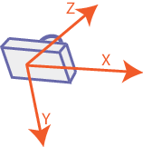
| 2016-11-03 08:04:38 -0600 | answered a question | Interpret results from triangulatePoints triangulatePoints returns 4 values per point. The first 3 are the coordinates of the point, but they all have to be divided by the fourth value. The coordinate system originates in the optical center of the first camera (left) with the x-axis pointing to the right, the y-axis pointing downwards (!) and the z-axis pointing away from the camera like this:
The units are the ones used during the calibration. For example I used a square size of 0.07m, so the results will be in meters as well. |
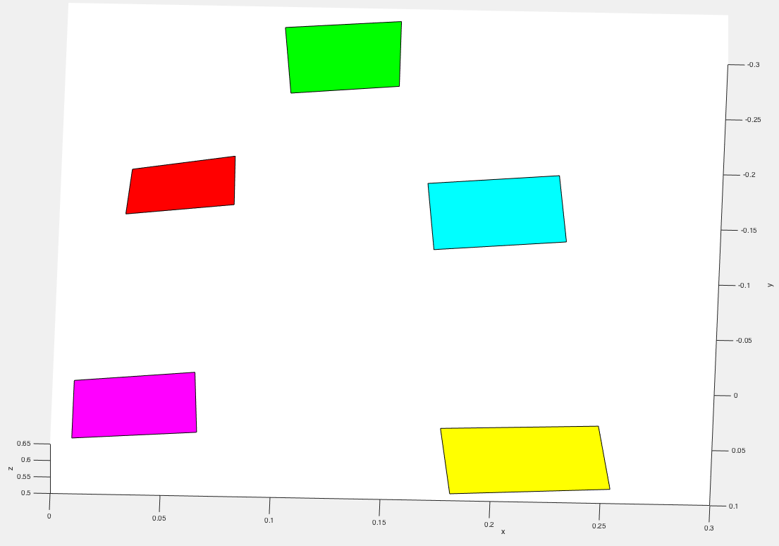
| 2016-11-03 07:35:06 -0600 | commented answer | Calculate 3D position from stereo Images Hi, thanks a lot for your comment! I did check with the calibration board as you suggested now, and I can see that the average distance between the squares is off by only 5mm at most (square size is 7cm so this is pretty good) and the distance to the camera has an error of about 10%, but the single points are just not very accurate (I never looked at the calibration board before, only at markers, and their position was always off when I objects on them so I thought I misread the values). I am going to update the question with a sample plot. I guess my problem was not really with the interpretation of the results, but just the results being bad. Probably the calibration was not as good as I thought. Do you have any tipps on how to do the calibration? How many snapshots should I use? |
| 2016-11-02 06:20:39 -0600 | commented answer | Calculate 3D position from stereo Images I use 0.07 as square size, since my squares are 0.07m wide. The object points are therefore at (0,0,0), (0,0.07,0)... I thought this was how to get the results scaled correctly, and that the results would be in the same units (m), but they are not. |
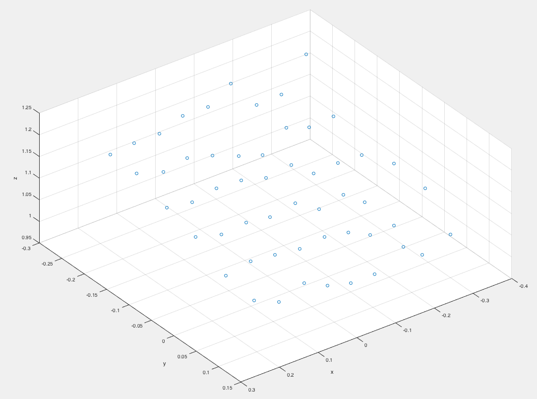
| 2016-11-01 05:55:58 -0600 | marked best answer | Calculate 3D position from stereo Images Hi, I have two images taken with a stereo-camera setup (calibrated). I detect markers in both images using the aruco contrib module. How can I calculate the 3D position of the markers edges from the two 2D positions? I found tutorials on how to calculate the depth map, but I do not need the map of the whole image, but just the corners of the markers. This is a sample plot of the values I get with triangulatePoints on the calibration checkerboard.
|
| 2016-11-01 05:55:50 -0600 | commented answer | Calculate 3D position from stereo Images @Tetragramm: Do you know how to interpret the results of triangulatePoints? It seems the coordinates are relative to the first camera, but in what units? I can't figure this out. Shouldn't the units be the same as the once used for the square size in the calibration? |
| 2016-11-01 05:53:15 -0600 | commented question | Interpret results from triangulatePoints Does anybody have an idea? |
| 2016-10-31 08:24:08 -0600 | commented question | run stereo vision on a stereo video data using open cv Are there any white-spaces in the filenames or the folders they are in? Try to specify the absolute path to the files and make sure there are no white-spaces in them! I do not know about stereoBM or SGBM |
| 2016-10-19 05:20:28 -0600 | commented question | Interpret results from triangulatePoints I updated the question with newer results and the plots, so please disregard the last two comments |
| 2016-10-19 05:19:20 -0600 | edited question | Interpret results from triangulatePoints Hi,
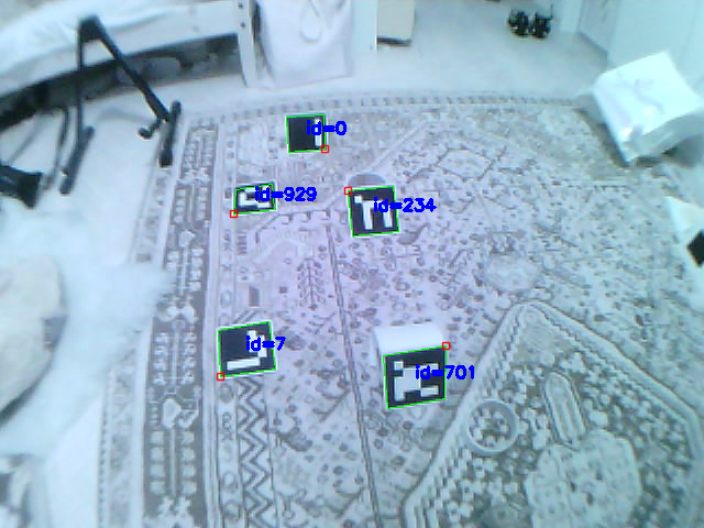
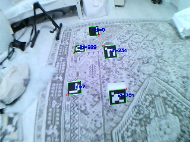
I am detecting ArUco Markers with a stereo setup and would like to know the 3d coordinates of the corners. I am using triangulatePoints to achieve that (the rig is fully calibrated and I am calling undistortPoints before triangulating), but I do not understand how to interpret the results. Here is an example:
As you can see the markers are detected fine. The results of triangulatePoints are the following: I tried to plot these in Matlab, and the result looks good:
But I just cannot find any relations to the cameras position. I would like to have coordinates somehow relative to one of the cameras, so that the camera is the origin of the used coordinate system. How can I do that? I read that the origin is the optical center of the first camera, but then my x-values should not be all-positive, right? |
| 2016-10-19 05:05:54 -0600 | commented question | Estimating rotation Matrix. OpenCV If the cameras are fixed, why don't you use something with lots of features so the matrixes are all generated? Afterwards you can use those matrixes for images with not many features. |
| 2016-10-18 11:20:51 -0600 | commented question | Interpret results from triangulatePoints I pursued this further and got some better calibration results by changing the flags, but I still cannot make use of the 3D points. These are some points I got now: |
| 2016-10-18 11:11:03 -0600 | commented question | Different behaviour of OpenCV Python arguments in 32 and 64-bit systems @adrita you might want to open a new issue on github so someone looks into this. |
| 2016-10-18 11:08:54 -0600 | commented question | speed up remap with different maps per color channel I ended up doing the remap with Unity, but I am leaving this question here, maybe someone someday is going to answer it. |