This forum is disabled, please visit https://forum.opencv.org
| 2020-05-21 07:23:56 -0600 | received badge | ● Popular Question (source) |
| 2018-08-10 03:58:25 -0600 | received badge | ● Popular Question (source) |
| 2018-04-24 14:47:38 -0600 | received badge | ● Notable Question (source) |
| 2017-07-25 12:05:13 -0600 | received badge | ● Popular Question (source) |
| 2016-09-29 05:00:38 -0600 | asked a question | Pointer to image producing different results I'm doing the following: What I thought this was doing was giving me a pointer to the image data, however when i print out the memory in a debugger I get different values after I add the same offset to both (i.e. x/100 image.data+100 != x/100 im+100). Is my pointing not doing what I think it is and if so why? The reason I'm doing this is because I'm trying to port some mex stuff, and the whole function relies on a pointer to an rgb image and address offsetting. |
| 2016-09-16 02:32:41 -0600 | commented question | affine transformation between two triangles and copy region thanks for having a look, i added an edit. |
| 2016-09-15 07:09:21 -0600 | asked a question | affine transformation between two triangles and copy region I have two triangular regions, defined by their vertices. I am trying to find the transformation between them (aside from different scale from screen shot) so I can ultimately mask out a region using one, and insert that into the other region. There is a rotation and translation present.
Currently I am doing this, to no avail. I think the issue is with warpAffine, because srcMask is fine going into it, but dstMask is just empty after the call. Any ideas? EDIT: The triangles aren't the full images, they are just a corresponding pair of regions I'd like to map. warp_mat for this is something like: [0.2 -0.1 2200; -0.3 0.02 -2400]. The location of the regions is about 2000 apart so assuming those rotations are okay I think the affine transform was calculated correctly. I can copy the regions from the first image to the second fine, its just when I try to transform them I get nothing. warpAffine() "The function cannot operate in-place." well thats not helping... |
| 2016-02-11 10:37:52 -0600 | received badge | ● Student (source) |
| 2015-04-21 00:59:01 -0600 | received badge | ● Enthusiast |
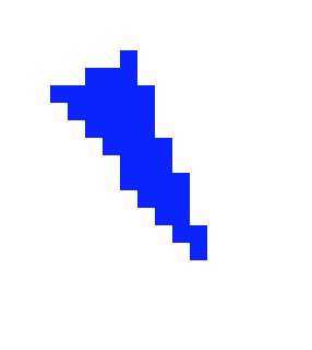
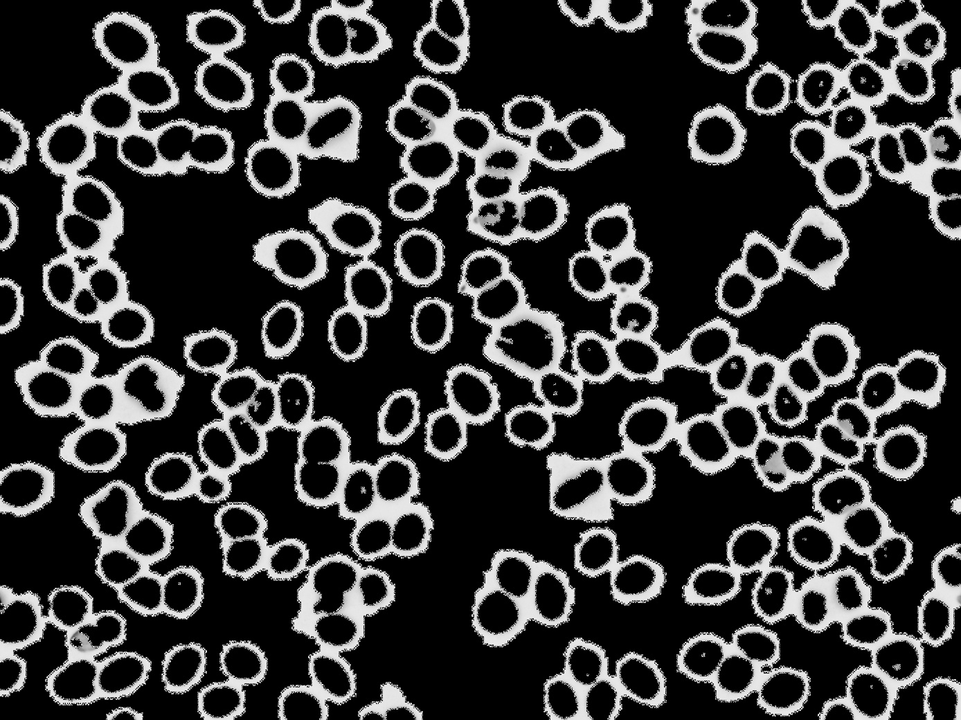
| 2015-04-20 20:23:10 -0600 | asked a question | Expansion/inversion of binary image Below I've segmented some cells, but I am trying now to essentially make the cells white and the rest black.The problem really is the white area around the cells - I'm not sure what the best approach would be. Any suggestions? I've been trying some morphological approaches but they don't seem to help. My current attempts basically have been using erosion/opening. I could do some contour work, but I would like to avoid that if possible.
|
| 2015-04-19 20:17:55 -0600 | asked a question | python imshow float64 I perform a 2D wavelet transform to build a pyramid representation of an image. When I imshow the reconstructed image (numpy float64 array), I get a white image, however when I imwrite the same image it is correct. Any idea what is happening when I use a float64 array? |
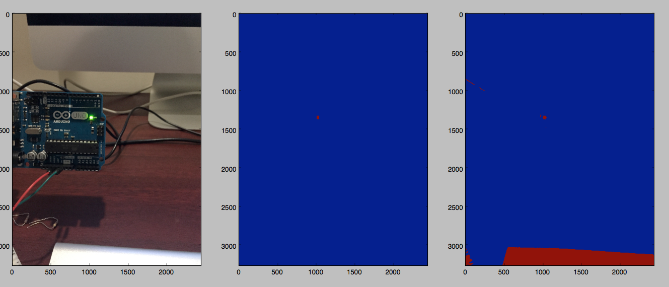
| 2015-04-09 05:44:20 -0600 | asked a question | Python efficiently filter blobs I'm segmenting an image and have a good threshold performed, however I need to remove areas which are too large or too small. My current implementation works, but I feel there has to be a quicker way. The general idea of this is shown below (trying to isolate the LED - the middle image is the end result). Are there any built in ways to achieve this more efficiently?
|
| 2014-11-04 03:15:20 -0600 | commented answer | Converting solvePnP tvec so if i offset my markerPoints all by half of the size it should give me the origin in the centre of the marker? |
| 2014-11-04 01:51:42 -0600 | commented answer | Converting solvePnP tvec I get where you're coming from, in the code I had it was placing stuff at (1.0,0) etc. Where did the 4 / 3 come from if the squares are 9 cm? And the negatives as well? |
| 2014-11-03 07:48:51 -0600 | received badge | ● Nice Answer (source) |
| 2014-11-03 03:34:24 -0600 | received badge | ● Teacher (source) |
| 2014-11-02 16:44:47 -0600 | asked a question | Converting solvePnP tvec I am using solvePnP to figure the rotation and translation of a fiducial marker relative to my camera (a Kinect). I understand that the units it will return for translation are the same as those I pass in, which in my case I think is the camera intrinsics: How can I convert the translation result to real world distance? Would I have to basically apply the fundamental camera matrix or is there a simple scaling factor I can apply? My current thought is to multiply tvec by the size of the marker (in my case an 8cmx8cm, so multiply by 8). EDIT: Having gained a bit more understanding, here is what markerPoints are: And sceneCorners are in pixels. Still can't quite get it to make 100% sense. |
| 2014-11-02 16:40:21 -0600 | answered a question | Can I pause traincascade? How? If you ctrl-c the program it will stop, leaving behind the partial xml files in the directory you specified. To continue with the training later, just run the traincascade with IDENTICAL parameters (don't change pictures either). It will continue on from the latest xml file. Partial stages will be re-evaluated. |
| 2014-11-01 23:56:22 -0600 | asked a question | solvepnp returning wrong rotation In C++ I have the following code locates a fiducial marker and attempts to solve for its translation and rotation relative to the camera. The translation vector seems right, but I rotation vector seems quite volatilve and wrong. It does draw the box around the marker it finds correctly. } |
| 2014-10-27 17:26:27 -0600 | received badge | ● Scholar (source) |
| 2014-10-27 17:02:50 -0600 | asked a question | Multi object tracking with Haar cascade detection I have an unknown number of objects on a rotating table and the goal is to track them individually. I have a robust cascade classifier trained and I can recover the metric location of the objects fairly accurately, the only problem is how to leverage OpenCV to keep track of each object. To make it a bit harder, all the objects are basically the same. What would my best approach be to 'lock on' to each object? Any suggestions would be appreciated. |
| 2014-10-08 05:40:14 -0600 | commented question | traincascade seg fault the parameters are being taken from a simple bash script, the script works fine. @abhishek i dont think that is the case, both the positives and negatives text files are correctly created from the images directories specified |
| 2014-10-07 15:31:57 -0600 | asked a question | traincascade seg fault OpenCV 2.4.9 OS X 16GB RAM. Any ideas why this crash? I've trained successfully with same data using feature size 20/30 and 20/20 with the buffers set to 4096. It seg faulted on 4096 with the new size 30/40 so I increased the buffers a bit. |
| 2014-09-15 17:27:23 -0600 | commented question | opencv_traincascade hanging with LBP tag trying LBP again using 99% of total CPU again and not doing a whole lot. |
| 2014-09-15 04:09:46 -0600 | commented question | opencv_traincascade hanging with LBP tag 2.4.9 running the compiled source found in the install directory |
| 2014-09-15 02:55:34 -0600 | commented question | Cascade training - negative images okay, ill edit with more detail. thanks guys. |
| 2014-09-13 22:04:17 -0600 | asked a question | opencv_traincascade hanging with LBP tag When I run this command: opencv_traincascade -data classifier -vec samples.vec -bg negatives.txt -featureType LBP -numStages 20 -minHitRate 0.999 -maxFalseAlarmRate 0.5 -numPos 100 -numNeg 750 -w 72 -h 24 -mode ALL -precalcValBufSize 1024 -precalcIdxBufSize 1024 The trainer is stuck at this stage indefinitely, using 99.x% of the CPU. This happens on Macs with both 4GB ram and 16GB ram. ===== TRAINING 0-stage ===== <begin pos="" count="" :="" consumed="" 100="" :="" 100="" neg="" count="" :="" acceptanceratio="" 750="" :="" 1<="" p=""> Without the -featureType LBP it runs fine seemingly and uses a reasonable amount of CPU (13%). My data is as follows: 11 initial positive images, 750 negatives -> create_samples returning 250 positive images. Am I doing something wrong? |
| 2014-09-13 19:08:33 -0600 | received badge | ● Editor (source) |
| 2014-09-13 19:08:33 -0600 | edited question | Cascade training - negative images Using the create samples application I can create an arbitrary amount of positive images from a small set (whilst not always the best option, it does save time). My first question is ideally what should the ratio be between positive and negative images (including the samples generated) - and does that affect the run time of opencv_train cascade. Im currently running a trainer with POS count = 1000, NEG count acceptanceRatio 750:1. My other questions are about the quality and size of negative images. Is there any advantage to having high resolution (several MB) negatives if the ultimate application of the detector is a Kinect camera? Also, does it matter what the negative images are? I just used random holiday photos for my first test and the quality of my detector wasnt brilliant. EDIT: The application is ultimately to detect various sizes of coffee cups in a crowded environment with varying lighting to do some 2d-3d mapping etc. As I understand, as the cups will all have rigid distinct geometric features with little variance, I don't entirely need to create a lot of distorted images with create_samples. I think it would be better to have a very wide negative library to cover for the varied lighting. Another question - how well should the positives be cropped? |