Ask Your Question
4

Detach blobs with a contact point

asked 2016-02-13 10:53:24 -0600

Drakem gravatar image

updated 2020-11-17 15:51:12 -0600

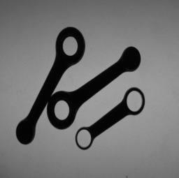
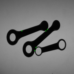
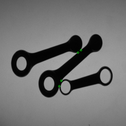
Hello. I'm working with blob analysis and i'm having problems on detaching 2 blobs which have a contact point. The images i'm working on are of this type:

image description image description

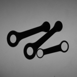
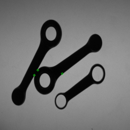
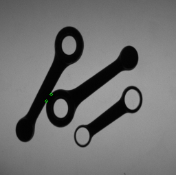
These are the same images binarized:

image description image description

My problem is morphological operators like erosion, dilation and opening don't work since the dimensions of the contact points are the same or even greater than some important points of the image (like the heads of the objects with 2 holes) and so when I set my operator (opening in this case) in order to delete contact points I end up deleting also parts of the image which I need to do other calculations (like number of holes per object).

I thought of applying a certain number of opening operators using a rectangle oriented as each of the objects as structuring element (as suggested here http://answers.opencv.org/question/56...), but this solution doesn't work well, since it is not assured that the contact points are oriented as one of the objects involved (as it happens, for example, for the contact point in the inferior part of the second image). Anyone of you have ideas of how I could solve this problem?

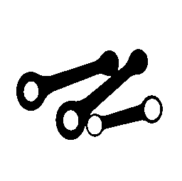
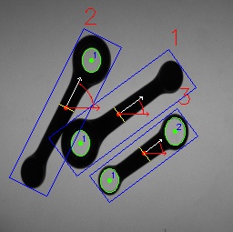
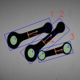
Edit: Here are the results thanks to sturkmen

image description image description

image description image description

edit retag flag offensive close merge delete

Comments

1

nice job ;-). Could you add also the code for drawing the coordinate axes with the curve. I like the way you draw it. It seems quite nice. Moreover, I think it would be better to post the code here, since in an external service it might get inactive after some period and get lost after all.

theodore gravatar imagetheodore ( 2016-02-14 10:45:23 -0600 )edit
2

Here's the code for the axes and the curve:

// Drawing orientation angle
float angle = -rod.orientation;
float length = rod.length/5;
ellipse(image, rod.barycenter, Size(rod.length/6,rod.length/6), 0, 0, -rod.orientation, Scalar(0,0,255));
Point2f P2;
P2.x =  (rod.barycenter.x + length * cos(angle * CV_PI / 180.0));
P2.y =  (rod.barycenter.y + length * sin(angle * CV_PI / 180.0));
arrowedLine(image, rod.barycenter, P2, Scalar(255,255,255));
P2.x =  (rod.barycenter.x + length * cos(0));
P2.y =  (rod.barycenter.y + length * sin(0));
arrowedLine(image, rod.barycenter, P2, Scalar(0,0,255));

Basically i draw 2 arrowed lines of certain length stasrting from barycenter, then i properly draw a portion of ellipse (circle) to draw the angle.

Drakem gravatar imageDrakem ( 2016-02-14 10:51:42 -0600 )edit

@Drakem well done ;-)

theodore gravatar imagetheodore ( 2016-02-14 17:11:31 -0600 )edit

2 answers

Sort by ยป oldest newest most voted
4

answered 2016-02-13 23:32:16 -0600

updated 2020-08-30 08:15:31 -0600

a trial code based on convexityDefects gives you some key points.maybe you will improve it or i will try to improve when i find time.

(also see smilar question i've answered with almost same code before.)

result images :

image description image description

#include <opencv2/highgui.hpp>
#include <opencv2/imgproc.hpp>
#include <iostream>

using namespace cv;
using namespace std;

int main( int argc, char** argv )
{
    Mat src = imread( argv[1] );
    if (src.empty())
        return -1;

    Mat bw;
    cvtColor( src, bw, COLOR_BGR2GRAY );
    bw = bw < 60;

    // Find contours
    vector<vector<Point> > contours;
    vector<int> contoursHull;
    vector<Vec4i> defects;
    findContours( bw, contours, RETR_EXTERNAL, CHAIN_APPROX_NONE );

    for ( size_t i = 0; i < contours.size(); i++)
    {
        if( contourArea(contours[i]) > 500 )
        {
            approxPolyDP(contours[i],contours[i],9,true);
            convexHull(contours[i], contoursHull,true);
            convexityDefects(contours[i], contoursHull,defects);

            for ( size_t j = 0; j <  defects.size(); j++)
            {
                Vec4i defpoint = defects[j];
                circle(src,contours[i][defpoint[2]],2,Scalar(0,255,0),1);
            }
        }
    }
    imshow("result", src);
    waitKey();
    return 0;
}

EDIT 1: i tried to improve my solution by checking nonzero pixels count around the defect point.

result is perfect for the test images.

image description image description

#include <opencv2/highgui.hpp>
#include <opencv2/imgproc.hpp>
#include <iostream>

using namespace cv;
using namespace std;

int main( int argc, char** argv )
{
    Mat src = imread( argv[1] );
    if (src.empty())
        return -1;

    Mat bw;
    cvtColor( src, bw, COLOR_BGR2GRAY );

    bw = bw < 60;

    // Find contours
    vector<vector<Point> > contours;
    vector<int> contoursHull;
    vector<Vec4i> defects;
    findContours( bw.clone(), contours, RETR_EXTERNAL, CHAIN_APPROX_NONE );

    for ( size_t i = 0; i < contours.size(); i++)
    {
        if( contourArea(contours[i]) > 500 )
        {
            approxPolyDP(contours[i],contours[i],2,true);
            convexHull(contours[i], contoursHull,true);
            convexityDefects(contours[i], contoursHull,defects);

            for ( size_t j = 0; j <  defects.size(); j++)
            {
                Vec4i defpoint = defects[j];
                Point pt = contours[i][defpoint[2]]; // get defect point
                Rect r3x3(pt.x-2, pt.y-2, 5, 5 ); // create 5x5 Rect from defect point

                // maybe no need but to be sure that the rect is in the image
                r3x3 = r3x3 & Rect(0, 0, bw.cols, bw.rows );

                int non_zero_pixels = countNonZero( bw(r3x3) );
                cout << non_zero_pixels << endl;
                if( non_zero_pixels > 17 )
                    circle(src,contours[i][defpoint[2]],2,Scalar(0,255,0),1);
            }
        }
    }
    imshow("result", src);
    waitKey();
    return 0;
}
edit flag offensive delete link more

Comments

Thank you very very much, that worked like a charm! I adapted your code to draw a line through the defect points and wrote an algorithm to fix some imperfections (in the second image case, the line go through the little blob head, resulting into opening the hole, so my algorithm does a sort of reconstruction of the image border). I edited the original post with the results.

Drakem gravatar imageDrakem ( 2016-02-14 08:25:58 -0600 )edit

glad it helped. but how did you choose the right points to draw line? it will be nice if you post your final code.

sturkmen gravatar imagesturkmen ( 2016-02-14 08:37:40 -0600 )edit
2

I implemented a very naive selection, iterating on every couple of defect points (excluding the couple (x,x) of course) and thresholding the L2 distance between the points of the couple. I tuned the threshold until in worked, but i know this is not a very robust implementation. I could improve it connecting one defect point to the nearest one, as Tetragramm suggested below. Anyway, i added the code to the original post.

Drakem gravatar imageDrakem ( 2016-02-14 08:52:22 -0600 )edit
1

answered 2016-02-13 15:49:58 -0600

Tetragramm gravatar image

I see two possible ways of doing this.

One, detect circles and when two run into each other, you can cut it there. Getting this to work reliably may be difficult.

Two, more likely to work, is to characterize the contour on the outside edge. It should never have a corner tighter than 90 degrees. From there, draw a straight line to the nearest other <90 degree corner and split it. Unfortunately, I don't have quite enough experience using the contours to know how to do that in code.

edit flag offensive delete link more

Question Tools

3 followers

Stats

Asked: 2016-02-13 10:53:24 -0600

Seen: 20,337 times

Last updated: Aug 30 '20