Ask Your Question
0

Use a camera to detect an object and mark it in the real world with a beamer

asked 2015-01-30 04:43:25 -0600

Graf gravatar image

updated 2015-02-04 16:00:24 -0600

Hey guys!

I try my luck to find out if the task in my head is actual (for me) possible to accomplish.

Using my OpenCV + Raspberry Pi + Camera Modul to detect an object. So far so good. Now i want to use my little LED Beamer to display a circle around the object. In the real world i will not be able to place my camera in a perfect position to the "play field".

Is it possible to calculate the difference from the real world to the internal resolution/ picture (1280x800)?

Thanks!

image description image description

edit retag flag offensive close merge delete

Comments

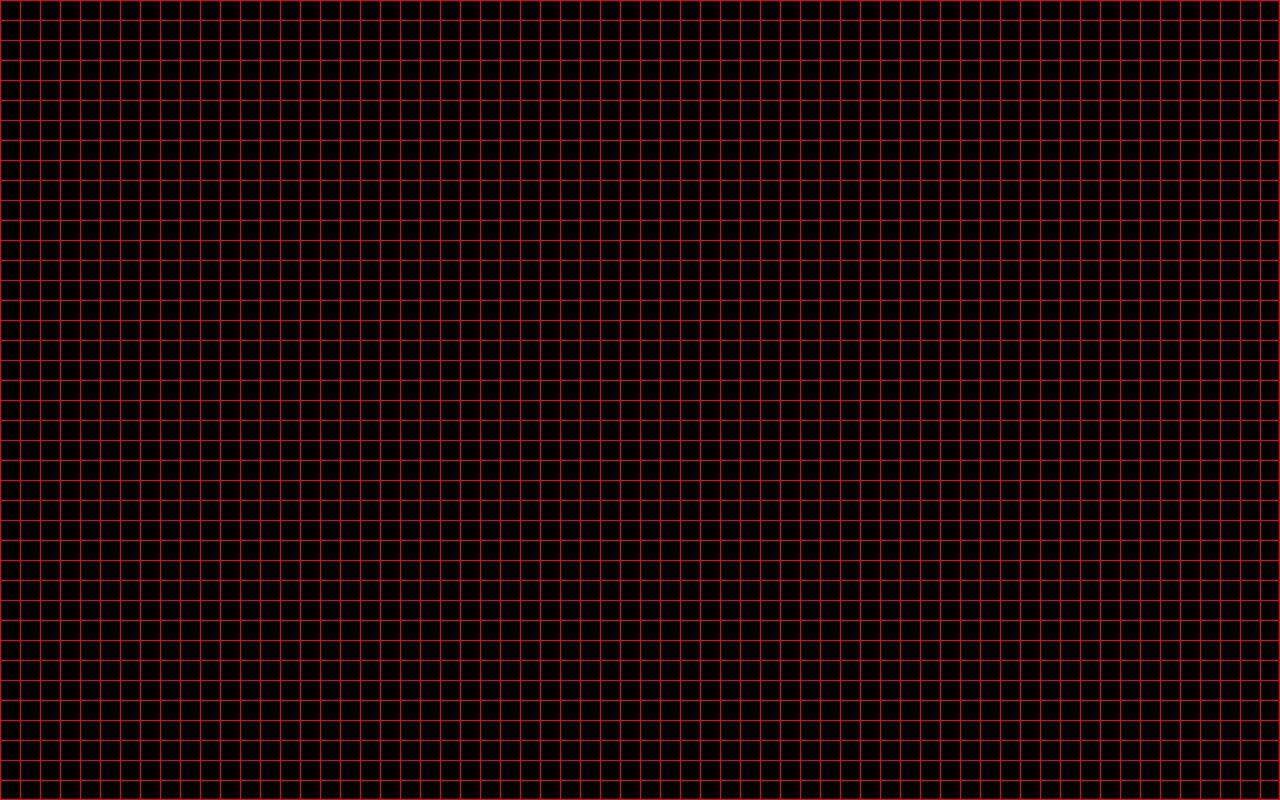
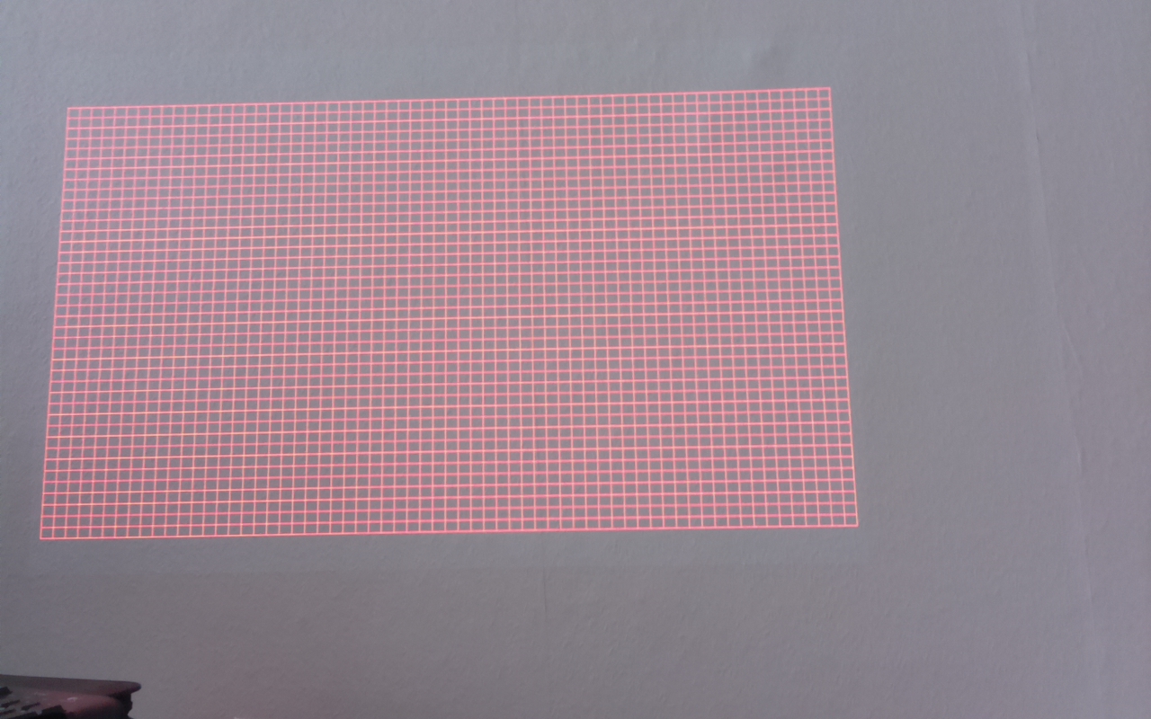
I updated my question and added 2 images. First is a raster made with pygame and second is a picture taken by the Raspberry PI NoIR cam.

I was thinking if it may be possible to mask, cut and resize the camera picture and the raster using OpenCV. Since i know the raster is 1280x800, i just have to find a way to match it. Is it possible to tilt and resize it so i can use this way to get what i want? It may even use less cpu resources, maybe...

Graf gravatar imageGraf ( 2015-02-04 16:06:35 -0600 )edit

2 answers

Sort by ยป oldest newest most voted
2

answered 2015-01-30 15:08:58 -0600

updated 2015-01-31 04:04:45 -0600

Your setup is basically a stereo setup. Cameras and projectors are very similar and can almost be treated the same for many computer vision applications. For both systems, a pixels is identified with a direction in the world. For a camera, all points that lie on a line towards the camera are seen at the same pixel (modulo distorition). And for a projector, all points that lie on such a line are illuminated if a certain pixel is set to a color.

One approach to calibrate your system is to project a pattern onto a planar surface (e.g. a large piece of flat cardboard). This pattern can be detected with the camera so that you have corresponding pixels on both systems. This information can be feed to the same algorithms that calibrate a stereo setup in which two cameras see the same marker points.

Maybe this can give you a rough direction. I wrote my master thesis about a sandbox with a projector/Kinect setup where I measured the positions with this approach. (Although it's a bit easier if you have a 3d Camera and not only a 2d)

A second approach (maybe similar to what secrestb meant in his answer):

Print a checkerboard pattern and fix it somewhere where both the camera and the projector can see it. With the calib3b-functions it's easy to get it's relative position to the camera. The points on the board are now your 3d marker for calibrating the projector (both intrinsic and extrinsic calibration relative to the camera). As the projector cannot see the pattern, you have to help him a bit. Move your mouse on the projector image until it points to the first corner of the projected pattern (the mouse icon is now visible on the printed checkboard at the first corner). Save this pixel position and continue until you have marked some points. Now you have pairs of 3d points (measured relative to your camera) and the corresponding pixels on your projector. This is almost exactly the information you also have when calibrating a camera with a marker. Therefore you can also use the calib3d-funtions used to calibrate a camera to calibrate your projector. You have to repeat that procedure for several marker positions to get both intrinsic and extrinsic calibration. [ if you know the intrinsics of your projector, a single view with some points is enough to get the extrinsic calibration]

edit flag offensive delete link more
-2

answered 2015-01-30 10:07:47 -0600

One approach would be a feedback loop. Take your best shot. The LED circle will show up on the camera. From there you should be able to make the circle larger or smaller, translate it left, right, up, or down as needed. Once you have it calibrated (correct scaling and correct translation) it should always work.

edit flag offensive delete link more

Comments

1

There is no way i can align the camera perfect. Even if i could succeed in this impossible task, i will never be able to move the camera or the projector/beamer again, not even for a tiny bit.

Graf gravatar imageGraf ( 2015-01-30 12:30:22 -0600 )edit

They don't need to be aligned perfectly, although they do need to significantly overlap. The point is to measure the amount of misalignment to change the projection. If for example, your circle is nearly perfect, but is one pixel too high (as seen in the camera), then re-project the circle one pixel lower. Once you know the correction factors needed (scaling, translation and maybe even rotation), you don't need a feedback loop anymore, just project using the correction.

secrestb gravatar imagesecrestb ( 2015-01-30 20:56:05 -0600 )edit

I think it would help if you explain a bit how you want to compute the calibration factors from your manual data.

FooBar gravatar imageFooBar ( 2015-01-31 02:20:27 -0600 )edit

The object is detected in camera space. The output (perhaps center pixel and radius) is the input to the projector translator which re-maps camera space to projector space. Because of resolution and misalignment camera space and projector space are not the same. The radius needs to be scaled so the circle is the correct size. The center needs to be scaled (to account for resolution difference) as well as moved/translated to account for misalignment. If you know the resolutions, (for example 1280X800 camera; 1024X768 projector) you can calculate the scaling (x 1024/1280 y 768/800 ). If not, project a large circle and measure it with the camera, then adjust the scaling until the circle size is what you want.

secrestb gravatar imagesecrestb ( 2015-01-31 05:22:31 -0600 )edit

Question Tools

1 follower

Stats

Asked: 2015-01-30 04:43:25 -0600

Seen: 1,128 times

Last updated: Feb 04 '15