Calculating depth with Ptr<StereoSGBM>, black bar on image
I have a calibrated fisheye stereo pair that I am using to create a depth map.
I send these rectified images:
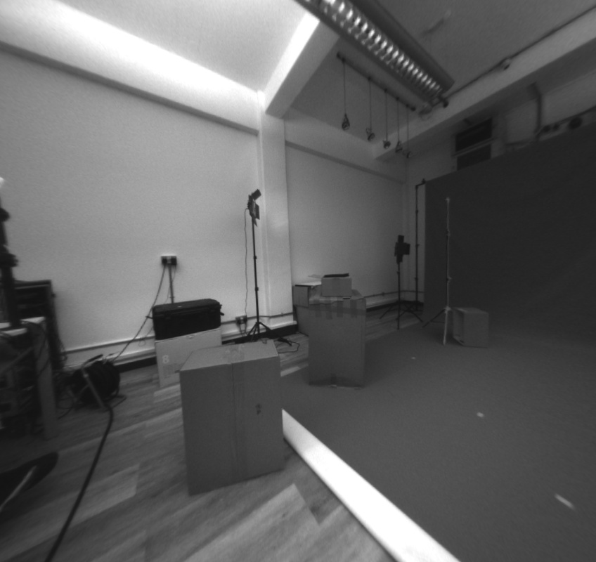
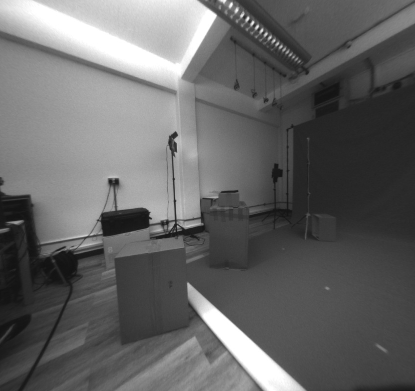
into the following function:
cv::Mat RGBDFunctions::ComputeDepth(cv::Mat left, cv::Mat right)
{
    bool no_downscale = false;

    int max_disp = MAX_DISPARITY;


    Mat left_for_matcher, right_for_matcher;
    Mat left_disp, right_disp;
    Mat filtered_disp;
    Mat conf_map = Mat(left.rows, left.cols, CV_8U);
    conf_map = Scalar(255);
    Rect ROI;
    Ptr<DisparityWLSFilter> wls_filter;
    double matching_time, filtering_time;


        if (!no_downscale)
        {
            max_disp *= DOWNSCALE;
            if (max_disp % 16 != 0)
                max_disp += 16 - (max_disp % 16);
            resize(left, left_for_matcher, Size(), DOWNSCALE, DOWNSCALE);
            resize(right, right_for_matcher, Size(), DOWNSCALE, DOWNSCALE);
        }
        else
        {
            left_for_matcher = left.clone();
            right_for_matcher = right.clone();
        }

        Ptr<StereoSGBM> left_matcher = StereoSGBM::create(0, max_disp, WIN_SIZE_SGBM);
        left_matcher->setP1(24 * WIN_SIZE_SGBM*WIN_SIZE_SGBM*SMOOTHING_FACTOR);
        left_matcher->setP2(96 * WIN_SIZE_SGBM*WIN_SIZE_SGBM*SMOOTHING_FACTOR);
        left_matcher->setPreFilterCap(MAX_X_GRAD);
        left_matcher->setMode(StereoSGBM::MODE_SGBM_3WAY);
        wls_filter = createDisparityWLSFilter(left_matcher);
        Ptr<StereoMatcher> right_matcher = createRightMatcher(left_matcher);

        matching_time = (double)getTickCount();
        left_matcher->compute(left_for_matcher, right_for_matcher, left_disp);
        right_matcher->compute(right_for_matcher, left_for_matcher, right_disp);
        matching_time = ((double)getTickCount() - matching_time) / getTickFrequency();


        wls_filter->setLambda(LAMBDA);
        wls_filter->setSigmaColor(SIGMA);
        filtering_time = (double)getTickCount();
        wls_filter->filter(left_disp, left, filtered_disp, right_disp);
        filtering_time = ((double)getTickCount() - filtering_time) / getTickFrequency();

        conf_map = wls_filter->getConfidenceMap();

        // Get the ROI that was used in the last filter call:
        if (!no_downscale)
        {
            // upscale raw disparity and ROI back for a proper comparison:
            resize(left_disp, left_disp, Size(), 1 / DOWNSCALE, 1 / DOWNSCALE);
            left_disp = left_disp / DOWNSCALE;
        }


    Mat raw_disp_vis;
    cv::ximgproc::getDisparityVis(left_disp, raw_disp_vis, VIS_MULT);

    Mat filtered_disp_vis;
    cv::ximgproc::getDisparityVis(filtered_disp, filtered_disp_vis, VIS_MULT);

    return filtered_disp_vis;

}
This gives me this depth map:
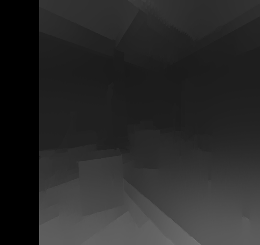
Which looks pretty good!
Except for the black bar on the side. What might be causing this?
Also, i am now trying to create a point cloud from this depth map, and am having huge trouble getting a good result. Is there any example code to create a cloud from depth?
Thank you!
The black bar is equivalent to your disparity search range. Those pixels cannot be searched for the entire range and so no result is returned. It doesn't have to be that way, but that was the decision of the implementer, probably something to do with vectorization and code simplicity.
The SGBM API can provide you a table relating disparity values to depths (presuming your cameras are calibrated correctly). Let's say your point cloud is a vector of (x,y,z) coordinates. Iterate over the columns and rows of your depth map image (each depth cell in turn). Project a point in the camera's coordinate space to the corresponding depth from the array, and append the resulting real world (x,y,z) coordinate to the point cloud vector. That's pretty much the high-level algorithm (I'm looking at some Robot Operating System code, but that's out of scope for answers in this forum - the lower level opencv and PCL code would need to do the same thing).
Hi, thank you for your answers. I am successfully creating a point cloud, using this:
It looks good, but I am not sure if the depth values are real-world correct.
Is this the correct approach?
Note that compute returns a 2d array with 16-bit fixed point disparity values, with the least significant 4 bits the fractional part. I'm not sure what kind of OutputArray the WLS Filter will return. Without going into it in detail, your arithmetic looks sensible enough for converting u,v via K (fx, fy, cz, cy) and disparity array to camera X,Y, Z. The official writeup on the relationships is at OpenCV: Camera Calibration and 3D Reconstruction. Your physical measurements should roughly equal your real world measurements, and will be more accurate when you take calibration, distortion (D) and rectification (stereo R|t transform for second camera) fully into account.