calibrateHandEye precision
Hi there!
I am using the calibrateHandEye functions from the Calib3d library to get the handEye calibration of a UR10 robot with a camera RealSense fixed to the end effector. After some problems I think, that I got to get the function work properly. But now I am seeing two things that do not fit completely, and I was hoping for a third opinion from your point of view.
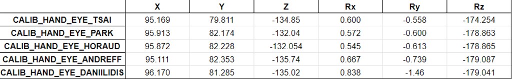
As you can see from the image below, I made 4 four measurements for each of the 5 methods that the function proposes. For each of the methods I used 10, 15, 18 and 20 robot poses with their respective pictures. From here I got a little confused:
- The first method (CALIB_HAND_EYE_TSAI) give completely different values depending on the amount of robot poses used. At the same time, and with the same values, the others 4 methods seem to converge to certain values close enough between them. Why is that?
- Though the values of the last 4 methods seem to converge, between them there are important differences. Why is that?
Thank you for the help!
The camera intrinsic parameters are:
std::vector<double> distortionCoefficients(5);  // camera distortion
distortionCoefficients[0] = 9.6349551984637724e-02;
distortionCoefficients[1] = -3.3260675111130217e-01;
distortionCoefficients[2] = 0;
distortionCoefficients[3] = 0;
distortionCoefficients[4] = 2.5833277679122602e-01;

double f_x = 1.2993539019658076e+03; // Focal length in x axis
double f_y = 1.2993539019658076e+03; // Focal length in y axis (usually the same?)
double c_x = 960; // Camera primary point x
double c_y = 540; // Camera primary point y

cv::Mat cameraMatrix(3, 3, CV_32FC1);
cameraMatrix.at<float>(0, 0) = f_x;
cameraMatrix.at<float>(0, 1) = 0.0;
cameraMatrix.at<float>(0, 2) = c_x;
cameraMatrix.at<float>(1, 0) = 0.0;
cameraMatrix.at<float>(1, 1) = f_y;
cameraMatrix.at<float>(1, 2) = c_y;
cameraMatrix.at<float>(2, 0) = 0.0;
cameraMatrix.at<float>(2, 1) = 0.0;
cameraMatrix.at<float>(2, 2) = 1.0;
Link to get the images and poses.
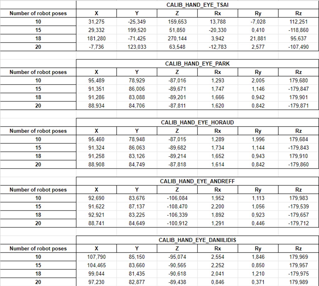
In the picture assume the ',' are '.' That´s the Spanish way, sorry for that. Is in mm and degrees
You may want to dump the values of
R_gripper2base,t_gripper2base,R_target2cam,t_target2camin some text files for each of the experiments, and possibly with the captured images of the chessboard. Roughly, you should be able to measure the translation between the camera and the gripper and say approximatively which one is the closest to the reality. Also, what is the output of the MVTec?Hi Eduardo! Good to see you again helping with this. I added to the original question a link to download the images and the matrixes with the robot poses. I couldn't upload the file directly here, don't know why. The approximate translation between the camera and tool was measured as: [100; 80; -130; 0; 0; 180] The results MVTec was giving: [100.147; 75.1024; -117.844; 0.89715; 359.675; 179.285]
Could you edit your question to add the camera intrinsic parameters?
Sure, it's done! I got the calibration with the same images of the link above.
The target2cam transformations look ok, here the images with the chessboard frame displayed.
I have compared the results with another library that gives the following transformation:
``` -0.9999710382 0.001876093187 -0.00737583906 87.59821339
-0.002064735358 -0.9996688056 0.02565182378 85.27051241
-0.007325271012 0.02566631001 0.999643727 -88.15990751
0 0 0 1
rx: -1.469942466 ; ry: -0.4226082804 ; rz: -179.8925048 ```
The hand-eye calibration process is a non-linear problem so I am not surprised having variable results (around the centimeter) between 10 and 20 data and between the last 4 methods. I am surprised by the inconsistency of the Tsai method though.
Thank you so much for the feedback, Eduardo. Also for me, the results of the Tsai method were weird. It seems like a bug. Great to have the results of the Visual Servoing Platform. I had some plans to give it a try as well. Now is not necessary. I need a precision of ~1mm in the calibration. Any way to increase precision?
For Hand-Eye calibration, I would use multiple images (20 is good in my opinion) acquired in a half-sphere in order to correctly cover the space and the rotation.
You may want to calibrate the camera with a non-symmetric chessboard pattern like this one if you use OpenCV for camera calibration. The chessboard pattern must be glued on a surface as flat as possible for accurate results. Also, check the reprojection error to have an idea of the quality of the camera calibration.
The offset in Z could be explained by the camera optical center position that can be hard to guess I think.
What's the difference in the chessboard you are suggesting? I don't see any difference, besides the size of the squares and the number of them. Could you please explain to me how to check the reprojection error of the camera calibration? I will try the tips you suggest. The offset in Z is anyway strange. The distance between the tool and the closer camera case side is 130mm. So the calibration values should be necessarily more than that. Since the camera itself is about 20mm depth, the value of Z should be around 130..150mm, shouldn't they?
The Tsai method can be easily checked using some other implementation. You can also try another toolbox (see the answer).
If you are doing image-based visual servoing, this control scheme is intrinsically immune to calibration errors. If you are doing pose-based visual servoing and want 1mm precision, you will have to carefully calibrate first the camera. This will be a long trial and redo process.