Wrong result in calibrateHandEye function [answered]

I am working in a robot application, in which I have a camera fixed to a robot gripper. In order to calculate the matrix transformation between the camera and the gripper Hcg I am using the calibrateHandEye new function provided in the OpenCV version 4.1.
In the next picture, you can see the description of the function from the OpenCV documentation
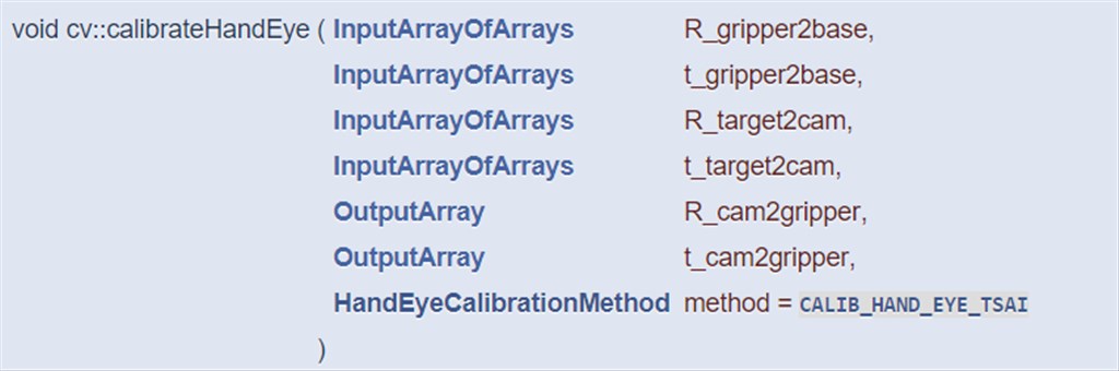
To use this function I am editing the camera_calibration example of samples\cpp\tutorial_code\calib3d\
I had taken 10 pictures of the chessboard from the camera mounted in the gripper and at the same time I recorded the robot position.
I changed the code, now It looks like:
// My_handeye.cpp : This file contains the 'main' function. Program execution begins and ends there.
//
#include <iostream>
#include <sstream>
#include <string>
#include <ctime>
#include <cstdio>
#include "pch.h"

#include <opencv2/opencv.hpp>
#include <opencv2/core.hpp>
#include <opencv2/core/utility.hpp>
#include <opencv2/imgproc.hpp>
#include <opencv2/calib3d.hpp>
#include <opencv2/imgcodecs.hpp>
#include <opencv2/videoio.hpp>
#include <opencv2/highgui.hpp>

using namespace cv;
using namespace std;

Mat eulerAnglesToRotationMatrix(Vec3f &theta);
Vec3f rotationMatrixToEulerAngles(Mat &R);
float rad2deg(float radian);
float deg2rad(float degree);

int main()
{

    // Camera calibration information

    std::vector<double> distortionCoefficients(5);  // camera distortion
    distortionCoefficients[0] = 2.4472856611074989e-01;
    distortionCoefficients[1] = -8.1042032574246325e-01;
    distortionCoefficients[2] = 0;
    distortionCoefficients[3] = 0;
    distortionCoefficients[4] = 7.8769462320821060e-01;

    double f_x = 1.3624172121852105e+03; // Focal length in x axis
    double f_y = 1.3624172121852105e+03; // Focal length in y axis (usually the same?)
    double c_x = 960; // Camera primary point x
    double c_y = 540; // Camera primary point y

    cv::Mat cameraMatrix(3, 3, CV_32FC1);
    cameraMatrix.at<float>(0, 0) = f_x;
    cameraMatrix.at<float>(0, 1) = 0.0;
    cameraMatrix.at<float>(0, 2) = c_x;
    cameraMatrix.at<float>(1, 0) = 0.0;
    cameraMatrix.at<float>(1, 1) = f_y;
    cameraMatrix.at<float>(1, 2) = c_y;
    cameraMatrix.at<float>(2, 0) = 0.0;
    cameraMatrix.at<float>(2, 1) = 0.0;
    cameraMatrix.at<float>(2, 2) = 1.0;

    Mat rvec(3, 1, CV_32F), tvec(3, 1, CV_32F);
    //

    std::vector<Mat> R_gripper2base;
    std::vector<Mat> t_gripper2base;
    std::vector<Mat> R_target2cam;
    std::vector<Mat> t_target2cam;
    Mat R_cam2gripper = (Mat_<float>(3, 3));
    Mat t_cam2gripper = (Mat_<float>(3, 1));

    vector<String> fn;
    glob("images/*.bmp", fn, false);

    vector<Mat> images;
    size_t num_images = fn.size(); //number of bmp files in images folder
    Size patternsize(6, 8); //number of centers
    vector<Point2f> centers; //this will be filled by the detected centers
    float cell_size = 30;
    vector<Point3f> obj_points;

    R_gripper2base.reserve(num_images);
    t_gripper2base.reserve(num_images);
    R_target2cam.reserve(num_images);
    t_target2cam.reserve(num_images);

    for (int i = 0; i < patternsize.height; ++i)
        for (int j = 0; j < patternsize.width; ++j)
            obj_points.push_back(Point3f(float(j*cell_size),
                float(i*cell_size), 0.f));

    for (size_t i = 0; i < num_images; i++)
        images.push_back(imread(fn[i]));

    Mat frame;

    for (size_t i = 0; i < num_images; i++)
    {
        frame = imread(fn[i]); //source image
        bool patternfound = findChessboardCorners(frame, patternsize, centers);
        if (patternfound)
        {
            drawChessboardCorners(frame, patternsize, Mat(centers), patternfound);
            //imshow("window", frame);
            //int key = cv::waitKey(0) & 0xff;
            solvePnP(Mat(obj_points), Mat(centers), cameraMatrix, distortionCoefficients, rvec, tvec);

            Mat R;
            Rodrigues(rvec, R); // R is 3x3
            R_target2cam.push_back ...
As you said, it could be an issue about the Euler convention. You should validate that you are able to correctly convert from Euler to rotation matrix.
Or better if you robot API allows it, use quaternion or rotation matrix directly.
The robot doesn´t give the quaternion or rotation matrix. I can only extract the information about the orientation as RPY Euler angles or rotation vector. I validated the correct conversion from Euler to rotation matrix. For example, using the first position I have: RPY angle: Rx= -153.61, Ry= 8.3, Rz= -91.91 The program is converting it correctly to
robot_rot_01 = [-0.03297927740105067, 0.9889760982746338, 0.1443560719490051;
0.8974292119750117, -0.03427269290003497, 0.4398251940045839;
0.4399240869640498, 0.1440544733526174, -0.8864057005072823]
So the problem is not there.
Maybe is the solvePnP function? I don´t fully understand how does it work. I tried to check that the positions it was generating was correct. At least the t_target2cam seems right, don´t know about R_target2c
If the robot API does not give rotation matrix, the only way to be sure that your conversion is correct is by looking at the robot manual about the convention they chose for Euler angles.
They are 12 different Euler angles conventions and you cannot verify that the output is correct by comparing with Matlab (unless the Euler convention is the same between the robot manufacturer and Matlab...).
What is the other software that does the Hand-eye calibration? If it is a software provided by the manufacturer, what is the reason to use the OpenCV version?
To verify that the transformation between the chessboard is correct, you can draw the chessboard frame in the calibration images and verify the translation roughly.
Also, verify that the frames are correct:
Hi Eduardo. Thanks for the interest. The other software is Halcon from MVTec. I got a trial license but is almost finished. And is very expensive. If I could solve that without that software, it will be great. I will try to check what you suggest about drawing the chessboard frame, though I am not very sure how to do it. The robot I am using is a Universal Robots UR10. It was difficult to find information about the convention they use, this is what I got so far:
the RPY (roll-pitch-yaw) rotations are extrinsic rotations about the X-Y-Z axes (corresponding to intrinsic rotations about the Z-Y’-X” axes)
Yeah, I checked the frames many times now the best I could...
Can you add the transformation estimated by MVTec?
Are you using the same input values between OpenCV and MVTec functions? From this documentation, it looks like
RobotPosesis the inverse transformation compared togripper2base.I rechecked the information of the robot, it seems that the rotation matrix is calculated in the way ZYX:
The RPY vector (Vector3d) in radians, describing a roll-pitch-yaw sequence of extrinsic rotations about the X-Y-Z axes, (corresponding to intrinsic rotations about the Z-Y’-X” axes). In matrix form the RPY vector is defined as Rrpy = Rz(yaw)Ry(pitch)Rx(roll).
Anyway, I am still getting a wrong result
No, the input values are different. MVTec uses a different calibration board, so the images are different and the poses are different as well. I am using this other function from MVtec.
The transformation I get from MVtec is CamInToolPose [0.10303, 0.0841074, -0.132758, 358.639, 359.273, 177.93]. That is in meters and degrees