Camera correction
Hello,
I have a problem with the following image acquired from a high resolution camera:
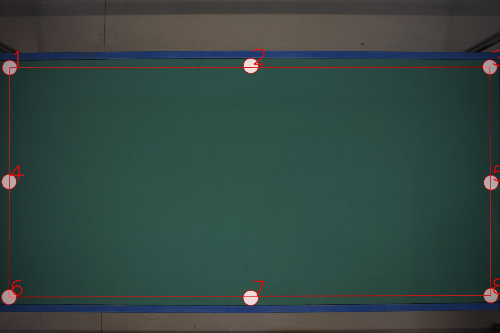
You can see that the upper and lower edges of the table are not parallel but slightly curved outwards. It is obvious when watching the line that is drawn between the corner circles that do not go through the centers of the upper and lower middle circles. I could use a piece of advice: what kind of distortion is this? At first I thought it is a perspective issue, since the small edges of the table are far away from the camera, but now I'm not so sure, it looks more like a fish-eye effect.
Also, what is the best option to correct this aberration? The tricky part is that I need the correction to be as accurate as possible (an item placed on the table should be detected as the same number of pixels anywhere on the table). Can I make use of the circles placed on the table (I can assume they are perfectly aligned) or do I need a chessboard? Is the chessboard calibration technique precise enough to cover this case?
Thanks
What you see is actually the optical distortion introduced by the lens and it can be corrected through the camera calibration procedure (with a quick search you'll find all the details). Once the camera is calibrated you will see that parallel features won't converge, but you will not get the second thing you need about circles being of the same size across the table because they are situated at different distances from the camera sensor: that's still a physical limit of the lens, unless you are using a telecentric one.
@David_86 Thank you for the information. If after camera calibration, the size difference comes from the distance to the detector, can't that be assimilated with a perspective warp?
It looks to me as a very difficult path to go by, because you would need to warp the image along concentric spheres with the origin on the camera sensor. Why do you need same size across all the field of view? With a calibrated camera you know the pixel/mm ratio (at a given distance of course) so you might use reference objects of known size to apply a correction as you move from the image center to the borders. That said without knowing the precision that you need for your application.
With the current configuration, the px/mm ration is ~= 1.6 and the requirement is a measurement precision of less than 1 mm. This has proven extremely difficult but I managed to find a solution. Items places in the center of the table are measured correctly, but as soon as they are moved towards the edge, the error stats piling up to 3mm near the edge. The problem with your latest suggestion is that I sometimes need to measure distances across the entire table. In that case I would need to somehow compute an integral of the distortion in order to compensate.
@Radu Then forget what I said if your measurements need to be performed across all the FoV. By the way I suggest changing the approach: with your actual px/mm ratio and the precision required to be less than 1 mm means there's no space left for any minimum error in your detection strategy, whatever it is. As soon as you miss 1 pixel you're already out of tolerance, that's quite hard in my experience ;-) Might consider a multi-camera setup (or keeping only one but move it linearly to take more pictures) and then easily stitch images together, you'll reduce the optical distortion keeping your targets in the center of the FoV