Ask Your Question
0

Projecting Rays using OpenCV and Camera Matrix

asked 2017-12-21 12:38:34 -0600

Ahmed gravatar image

updated 2017-12-24 14:48:57 -0600

I would like to cast rays from the camera and check the intersected points on the table, which is I assume at (0,0,0) with normal (0,1,0).. so for example I choose a point on a table by mouse, then I cast rays from the origin (0,0,0) to the plane, but the problem is I get a false point, that is not on the plane but still positive.

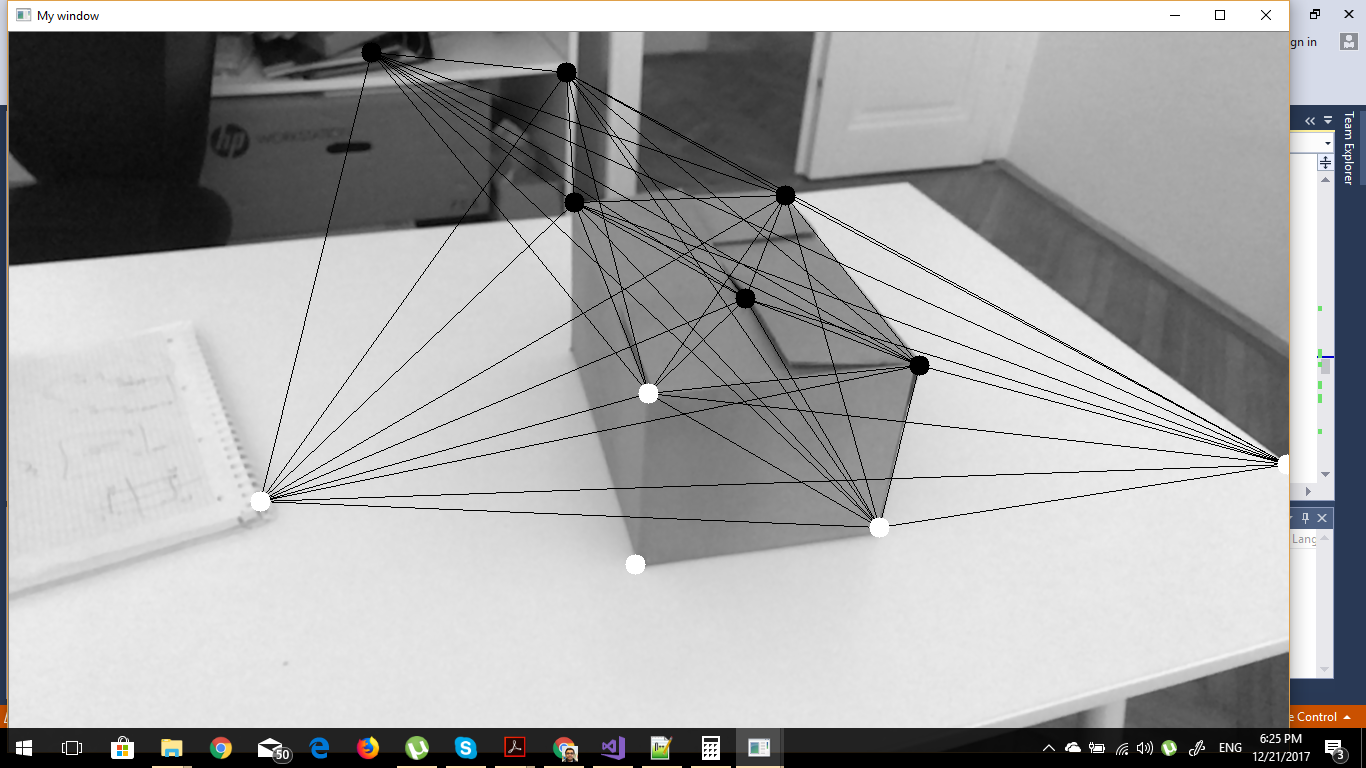
here is a picture to show what I'm doing

image description

//Generate a camera intrinsic matrix
            Mat K = (Mat_<double>(3, 3)
                << 1600, 0,src.cols/2,
                0, 1600,src.rows/2,
                0, 0, 1);


            Mat invCameraIntrinsics = K.inv();
            cout << "inv" << invCameraIntrinsics;
            std::vector<cv::Vec3d> pointsTransformed3D;

            std::vector<cv::Vec3d> points3D;
            for (int i = 0; i < corners.size(); i++)
            {
                cv::Vec3d pt;

                pt[2] = 1.0f;

                pt[0] = (corners[i].x );
                pt[1] = (corners[i].y );

                points3D.push_back(pt);
            }

            cv::transform(points3D, pointsTransformed3D, invCameraIntrinsics);


            Mat rot = (Mat_<double>(3, 3)
                << 0.8744617, 0.2258282, -0.4293233,
                0.0608088, 0.8270180, 0.5588771,
                0.4812683, -0.5148232, 0.7094631);

            std::vector<cv::Point3d> pointsRotated;
            Mat translVec(3, 1, CV_64F);
            translVec.at<double>(0, 0) = 21.408294677734375;
            translVec.at<double>(1, 0) = 531.1319580078125;
            translVec.at<double>(2, 0) = 705.74224853515625;

            const Mat camera_translation = (-rot * translVec);
            cv::transform(pointsTransformed3D, pointsRotated, rot.inv());

            std::vector<Ray> rays;
            for (int i = 0; i < pointsRotated.size(); i++)
            {

                Ray ray;

                ray.origin = Vec3f(camera_translation.at<double>(0,0), camera_translation.at<double>(1,0),
                    camera_translation.at<double>(2,0));
                ray.direction = Vec3f(pointsRotated[i][0], pointsRotated[i][1], pointsRotated[i][2]);

                rays.push_back(ray);
            }
            std::vector<cv::Vec3f> contacts;

            for (int i = 0; i < pointsRotated.size(); i++)
            {
                Vec3f pt(0, 0,0);

                cv::Vec3f contact;
                std::pair<bool, double> test = linePlaneIntersection(rays[i].direction, rays[i].origin, Vec3f(0, 1, 0), pt);
                if (test.first == true)
                {
                    cv::Vec3f contact(rays[i].origin + (rays[i].direction) * test.second);
                    contacts.push_back(contact);
                }
            }
edit retag flag offensive close merge delete

Comments

It looks like you're generating the rays correctly, but you do know that the camera is (0,0,0) in that coordinate system, right? So the table would be somewhere at a positive z, which does not match what you said.

I would expect all of the Rays there to have a +z axis.

Tetragramm gravatar imageTetragramm ( 2017-12-21 19:00:54 -0600 )edit

Thanks for your comment. I know the position of the camera... should I generate the the ray from the origin (position) of the camera ?

Ahmed gravatar imageAhmed ( 2017-12-22 02:50:38 -0600 )edit

Yes. The line of sight is from the camera, therefore your ray should be too.

Tetragramm gravatar imageTetragramm ( 2017-12-22 21:11:21 -0600 )edit

How about transforming the 2D points into 3D points ? is the above code correct ? or should I use the ViewMatrix and get the inverse of it then transform the 2D points into 3D using that inverse matrix ?

Ahmed gravatar imageAhmed ( 2017-12-23 02:22:37 -0600 )edit

That's correct. Of course, there's no depth information, but that's what your plane is for.

Tetragramm gravatar imageTetragramm ( 2017-12-23 10:19:00 -0600 )edit

Thanks. So the problem of measuring the cube is reduced to Finding 3D positions, generate rays from the Camera position into the plane(the table) and see intersected points, then find perpendicular lines ?

Ahmed gravatar imageAhmed ( 2017-12-23 13:32:01 -0600 )edit

Yep. The hardest part of that is probably the camera position relative to the table, but ARUCO markers provide an easy solution to that if you don't already have one.

Tetragramm gravatar imageTetragramm ( 2017-12-23 15:40:12 -0600 )edit

Thanks. How would I convert those corner points into 3D positions ? I'm having problem with that

Ahmed gravatar imageAhmed ( 2017-12-24 05:52:06 -0600 )edit

1 answer

Sort by » oldest newest most voted
1

answered 2017-12-24 08:52:58 -0600

Tetragramm gravatar image

You say you've got the camera position and orientation, and the table is defined as a plane passing through (0,0,0)

You create the pointsTransformed3D just like you do, then also multiply it by the inverse rotation matrix of the camera, just like HERE. Then it's origin is the location of the camera (see the camera_translation variable in that function).

Finding the intersection is easy: https://en.wikipedia.org/wiki/Line–plane_intersection

edit flag offensive delete link more

Comments

Thanks so much. If I have the position and orientation of the target ( the cube), how would I calculate the position and orientation of the Camera ?

Ahmed gravatar imageAhmed ( 2017-12-24 09:04:07 -0600 )edit

Please see the updated post and code. I did exact as you did, besides fitting lines. I draw the fitted lines, I get fully distorted lines, am I doing something wrong ?

Ahmed gravatar imageAhmed ( 2017-12-24 14:47:15 -0600 )edit

here is full code https://pastebin.com/HJZdCH12 and sample image https://imgur.com/a/qfPEL

Ahmed gravatar imageAhmed ( 2017-12-24 15:20:54 -0600 )edit

Please help me, I have been struggling a lot

Ahmed gravatar imageAhmed ( 2017-12-26 04:16:39 -0600 )edit

How did you get the rotation and translation? I've tried plotting the coordinate system axes with drawAxis, and I can't see them within the image.

I suspect those are wrong. Also, the camera matrix looks artificial, not calibrated.

Tetragramm gravatar imageTetragramm ( 2017-12-26 17:10:20 -0600 )edit

Here is the position and orientation of the camera https://pastebin.com/YFXcQLEJ Gyroscope is the position and orientation of the Camera. Thanks a lot !

Ahmed gravatar imageAhmed ( 2017-12-26 17:37:51 -0600 )edit

So this is a cell-phone or similar? That position and orientation does not work for this scenario. You need the rvec and tvec relative to the plane of the table, not wherever the phone happened to be when it started.

Tetragramm gravatar imageTetragramm ( 2017-12-26 17:41:30 -0600 )edit

it's actually relative to the plane of the table( which is ) the target, yes its a cell phone

Ahmed gravatar imageAhmed ( 2017-12-26 17:45:08 -0600 )edit

Hmm, Those values do not match what is in the "full code" link. Where is the origin of the system? One of the table corners?

Tetragramm gravatar imageTetragramm ( 2017-12-26 21:15:18 -0600 )edit

Yes one of the corners

Ahmed gravatar imageAhmed ( 2017-12-27 01:11:45 -0600 )edit

Question Tools

1 follower

Stats

Asked: 2017-12-21 12:38:34 -0600

Seen: 3,762 times

Last updated: Dec 24 '17