Ask Your Question
1

register ir image to distorted rgb

asked 2017-04-10 10:04:09 -0600

theodore gravatar image

updated 2017-04-10 10:11:00 -0600

Hi guys, I need some help/hints regarding the following problem. I have an rgb and an ir image of the same scene but in different resolution.

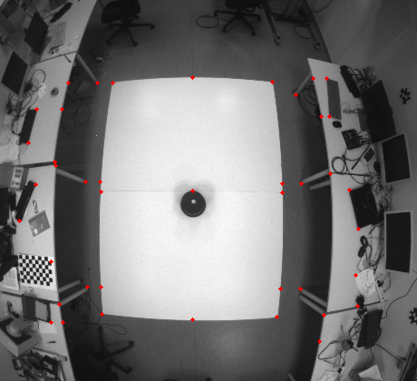
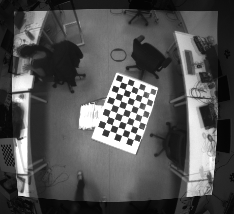
RGB image (420x460):

image description

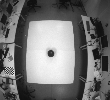
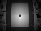
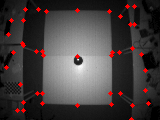
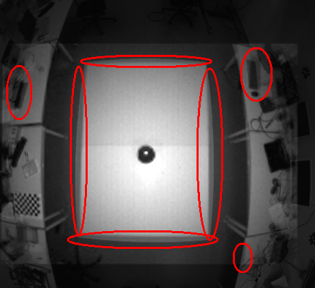
and the ir corresponding (120x160):

image description

Now I want to register the ir image to the distorted RGB one. The way I am doing it at the moment is by extracting the homography between the two images and then applying the transformation to the ir image. My upper goal is to use this transformation to the depth output and since the ir with the depth sensor output are aligned I am using the ir images since I can have access to more visual information. In the beginning I tried to use an automatic keypoints detector algorithm like SURF (it seems to perform a bit better, in regards to others) however the result is not that good since also the points that if finds are not that accurate as you can see below:

Keypoints detected:

image description

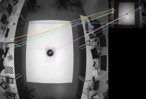
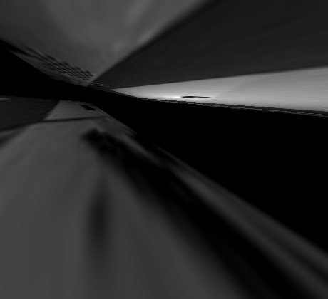
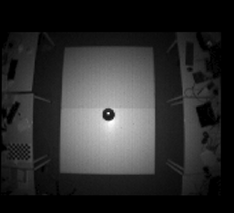
Registration based on the above keypoints (not good at all):

image description

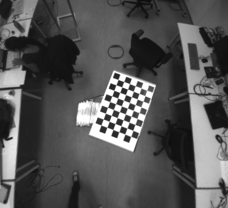
I tried other keypoint detection algorithms as well but the result though it might improved it was not acceptable. Therefore, I decided to provide the matching points manually:

image description image description

the registered image is by far much better now

image description

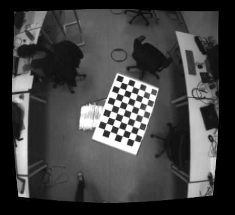
and if I overlay the two images

image description

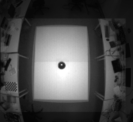
However, you will notice that there is a kind of misplacement (or not good registration) in some spots:

image description

Therefore, I was just wondering if there is a way to get a better result from what I am getting already. Note that I need to keep the distortion in the rgb image, therefore following the normal procedure (chessboard, extracting intrinsic/extrinsic coeffs, undistort, rectify, etc...) is out of the grid for the moment at least.

Thanks.

Adiitional code:

#include <iostream>
#include <stdio.h>
#include <opencv2/opencv.hpp>
#include "opencv2/core.hpp"
#include "opencv2/imgproc.hpp"
#include "opencv2/features2d.hpp"
#include "opencv2/highgui.hpp"
#include "opencv2/calib3d.hpp"
#include "opencv2/xfeatures2d.hpp"

using namespace std;
using namespace cv;
using namespace cv::xfeatures2d;

int main(int argc, char *argv[])
{
    cout << "Hello World!" << endl;

    Mat rgb = imread("../frame_5.png", IMREAD_GRAYSCALE);
    Mat ir = imread("../frame_5a.png", IMREAD_GRAYSCALE);


    if(!rgb.data || rgb.empty())
    {
        cerr << "Problem loading rgb image!!!" << endl;
        return -1;
    }

    if(!ir.data || ir.empty())
    {
        cerr << "Problem loading ir image!!!" << endl;
        return -1;
    }

    Mat ir2 = ir * 2;


    imshow("rgb", rgb);
    imshow("ir", ir);
    imshow("ir2", ir2);


    waitKey();


    //-- Step 1: Detect the keypoints and extract descriptors using SURF
    int minHessian = 400;

    Ptr<SURF> detector = SURF::create( /*minHessian*/600);
//    Ptr<BRISK> detector = BRISK::create(100);


    std::vector<KeyPoint> keypoints_object, keypoints_scene;
    Mat descriptors_object, descriptors_scene;
    detector->detectAndCompute( rgb, Mat(), keypoints_object, descriptors_object );
    detector->detectAndCompute( ir, Mat(), keypoints_scene, descriptors_scene );

    //-- Step 2: Matching descriptor vectors using FLANN matcher
    BFMatcher matcher(NORM_L2, true);
//    FlannBasedMatcher matcher;
    std::vector< DMatch > matches;
    matcher.match( descriptors_object, descriptors_scene, matches );
    double max_dist = 0; double min_dist = 100;
    //-- Quick calculation of max and min distances between keypoints
//    for( int i = 0; i < descriptors_object.rows; i++ )
    for( int i = 0; i < matches.size(); i++ )
    { double ...
(more)
edit retag flag offensive close merge delete

Comments

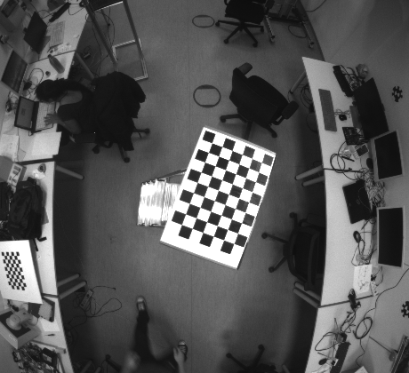
Normally, the homography relates the transformation between two planes. There is also something called "infinite homography" when the scene is very far and when the camera motion is purely (mostly) a rotation: it is this assumption that is made for image stitching if I am not wrong. This is why you should try to rotate around the camera optical center when taking pictures for a panorama to get the best results.

Eduardo gravatar imageEduardo ( 2017-04-10 10:27:34 -0600 )edit

Unfortunatelly the sensors are fixed in a position, therefore not possible to rotate around or move them even a bit (if this is what you mean).

theodore gravatar imagetheodore ( 2017-04-10 10:38:46 -0600 )edit

It is more a general comment about the fact that maybe the homography is not so well estimated as the chosen points do not lie on the same plane (points on the floor, points on the tables, ...). Also, I am not sure if the warping will be correct in this case (multiple planes)? I cannot tell as I don't have not so much experience with homography and image warping.

What I am sure is that the homography relates the transformation between two planar objects/scenes.

Eduardo gravatar imageEduardo ( 2017-04-10 10:49:19 -0600 )edit

actually @Tetragramm has a nice link to a paper here but I am not sure how directly is related to what I want to achieve, I was also trying to see if I can find their code but no success

theodore gravatar imagetheodore ( 2017-04-10 11:27:07 -0600 )edit

@theodore I have edited my answer with a sample code to align a color image to a depth/IR image.

Eduardo gravatar imageEduardo ( 2017-04-14 10:19:56 -0600 )edit

@Eduardo thanks. I'll have a look.

theodore gravatar imagetheodore ( 2017-04-18 06:52:21 -0600 )edit

3 answers

Sort by ยป oldest newest most voted
0

answered 2017-04-10 10:44:02 -0600

Eduardo gravatar image

updated 2017-04-14 10:16:19 -0600

If I have understood the question correctly, what you want is to register the IR image with the color image. The depth image is aligned with the IR image.

In this case, you should be able to use the same principle than what should be used for the popular depth sensor APIs (Kinect API, librealsense, etc.):

  • assuming the depth/IR and the color sensors are rigid and calibrated (known transformation between the two sensors)
  • assuming the depth/IR and the color sensors are calibrated (known intrinsic parameters)
  • for a [u,v] coordinate in the depth image frame, you should be able to compute the 3D coordinate [X, Y, Z] in the depth frame
  • you can transform a 3D point in the depth frame to the color frame using the homogeneous transformation matrix ([R|t])
  • you can then project the 3D point in the color frame using the color intrinsic parameters to get the correspond pixel color at the [u,v] depth/IR image coordinate

See for instance in the librealsense sample the code that performs the registration.

Edit:

The following code should demonstrate how to align a color image to a depth/ir image:

cv::Mat rvec_depth2color; //rvec_depth2color is a 3x1 rotation vector
cv::Rodrigues(R_depth2color, rvec_depth2color); //R_depth2color is a 3x3 rotation matrix

std::vector<cv::Point3d> src(1);
std::vector<cv::Point2d> dst;
cv::Mat color_image_aligned = cv::Mat::zeros(color_image.size(), color_image.type());
for (int i = 0; i < depth_image.rows; i++) {
  for (int j = 0; j < depth_image.cols; j++) {
    //Check if the current point is valid (correct depth)
    if ((*pointcloud)(j,i).z > 0) { //pointcloud is a pcl::PointCloud<pcl::PointXYZ>::Ptr in this example
      //XYZ 3D depth coordinate at the current [u,v] 2D depth image coordinate
      cv::Point3d xyz_depth( (*pointcloud)(j,i).x, (*pointcloud)(j,i).y, (*pointcloud)(j,i).z );
      src[0] = xyz_depth;

      //Transform the 3D depth coordinate to the color frame and project it in the color image plane
      cv::projectPoints(src, rvec_depth2color, t_depth2color, cam_color, dist_color, dst);
      cv::Point2d uv_color = dst.front();

      //Clamp pixel coordinate
      int u_color = std::max( std::min(color_image.cols-1, cvRound(uv_color.x)), 0 );
      int v_color = std::max( std::min(color_image.rows-1, cvRound(uv_color.y)), 0 );

      //Copy pixel
      color_image_aligned.at<cv::Vec3b>(i,j) = color_image.at<cv::Vec3b>(v_color, u_color);
    }
  }
}
edit flag offensive delete link more

Comments

you understood correctly about the resistration. What you did not get is that I want to register the ir/depth image to the distorted rgb image, threfore I cannot follow the normal principle, right? please correct me if I am wrong.

theodore gravatar imagetheodore ( 2017-04-10 10:58:02 -0600 )edit

If you know the distortion coefficients, the only difference is to project by taking into account the distortion coefficients?

  • [u,v]d is 2D depth image coordinate
  • [x,y,1]d is 3D coordinate in the normalized depth frame (z=1) obtained using undistortPoints() and the distortion coefficients of the depth sensor
  • [...]
  • [X,Y,Z]c is 3D coordinate in the color frame
  • project in the color image frame using the intrinsic parameters + distortion coefficients of the color sensor

See for example rs_project_point_to_pixel (lots of useful things in the librealsense API). Anyway, this is what I would do and not the homography thing but with very few experience on this topic .

Eduardo gravatar imageEduardo ( 2017-04-10 11:22:17 -0600 )edit

Also, with this method the image alignment / registration is general (as long as the color and the depth sensors are not moved and intrinsic / extrinsic parameters are known) and fully automated.

Eduardo gravatar imageEduardo ( 2017-04-10 11:27:45 -0600 )edit

@Eduardo thanks for your time, my experience is also not that deep. Thus, I am trying to figure out what I need to do. So if I understood correctly what you are saying is that I need to follow the common procedure with the chessboard, extract the intrinsic coeffs for each sensor, then extract the extrinsic coeffs between the two sensors and project the the depth image to the rgb by using the intrinsic+distortion coeffs of the color sensor?

theodore gravatar imagetheodore ( 2017-04-10 11:57:34 -0600 )edit

Yes. You need to calibrate the color and the depth (the IR in fact) sensors to get the intrinsic parameters + distortion coefficients + estimate the transformation between the color and depth sensors using for example stereoCalibrate().

Similar topics (without taking into account the distortion) for further reference:

The only difference with your case is that you want to keep the distortion effect but the procedure is the same. projectPoints() takes into account the distortion by the way.

Eduardo gravatar imageEduardo ( 2017-04-10 12:35:31 -0600 )edit

Here's some old code to re-distort an image. So calibrate both, undistort the IR, and then distort using the color coefficients.

http://code.opencv.org/issues/1387

Tetragramm gravatar imageTetragramm ( 2017-04-10 19:48:59 -0600 )edit
0

answered 2017-04-13 05:46:05 -0600

theodore gravatar image

updated 2017-04-18 07:12:44 -0600

ok I tried to obtain some better intrinsic and dist coeffs for the rgb camera. Then using the undistortion() function I undistorted the images and finally multiplying the dist coeffs with -1 and reapplying the undistortion() function I reapplied the distortion. However, you will notice that the result is wrong. Why this, is it due to not good calibration matrix or something else?

Original image:

image description

Undistorted image (how I do not zoom in here??????????)

image description

Redistorted image:

image description

Overlayed redistorted image to original (notice the bad allignement):

image description

edit flag offensive delete link more

Comments

You're using getOptimalNewCameraMatrix for initUndistortRectifyMap aren't you? There's a kind bug or two in that function, so if you simply use your original camera matrix for initUndistortRectifyMap, you should be ok. If there's too much or not enough black you can play with modifying the focal length in the camera matrix a bit to effectively zoom in or out.

Tetragramm gravatar imageTetragramm ( 2017-04-14 17:01:56 -0600 )edit

@Tetragramm for the simle undistortion I am using the normal undistort() function as it. I am not passing any newCameraMatrix at the end. I am using the initUndistortRectifyMap for the rectification procedure. In any case before I go there I would like to check whether my undistortion is fine. Check my latest post.

theodore gravatar imagetheodore ( 2017-04-18 07:03:12 -0600 )edit

keypoint coordinates to estimate homography are in undistort images ?

LBerger gravatar imageLBerger ( 2017-04-18 07:27:51 -0600 )edit

@LBerger forget about the homography, I am going with the normal calibration procedure now. The idea is to undistort both both sensors, rectify them and then re-apply the distortion coeffs of rgb sensor to both rectified images so that my depth values correspond to the distorted rgb image. However, you see that my redistorted rgb image is quite bad. I can expect some error but I think that this is too much, therefore I was wondering if this is due to bad initilal cameraMatrix values or am I doing something wrong?

theodore gravatar imagetheodore ( 2017-04-18 08:42:56 -0600 )edit

Ok about homography. "finally multiplying the dist coeffs with -1 and reapplying the undistortion() function" why do you mean ? (distance from center changed)

LBerger gravatar imageLBerger ( 2017-04-18 09:34:44 -0600 )edit

@LBerger I did what is proposed here, which it should be working right?

theodore gravatar imagetheodore ( 2017-04-18 09:55:49 -0600 )edit

Sorry but I do not stackoverflow link. I tried to reproduce results but I cannot with a basic webcam with no distortion visible. I think method is goodat first order. With a fisheye camera you should try method given I think it is wrong. may be you can find my mistake

int main(int argc, char* argv[])
{
Mat M=(Mat_<double>(3,3)<< 1.4075586700691963e+03, 0., 6.5546028282727559e+02, 0., 1.4133318814482820e+03, 4.8445043004432102e+02, 0., 0., 1.),P;
Mat D=(Mat_<double>(1, 5) << -4.6039721332885870e-02, 3.9222056998667748e-01, 0, 0, -1.0816634031802570e+00);
Mat pSrc=(Mat_<double>(10, 1)<<0,0,655,0,655,392,0,392,1280,960);
pSrc=pSrc.reshape(2);
Mat pDst;
cout<<M<<"\n";
cout<<-D<<"\n";
undistortPoints(pSrc,pDst,M,D,noArray(),P);
cout<<pSrc<<"\n";
LBerger gravatar imageLBerger ( 2017-04-18 14:26:46 -0600 )edit

// and

pDst=pDst.reshape(1);
pDst.col(0) = pDst.col(0)*M.at<double>(0, 0) + M.at<double>(0, 2);
pDst.col(1) = pDst.col(1)*M.at<double>(1, 1) + M.at<double>(1, 2);
pDst = pDst.reshape(2);
cout<< pDst <<"\n";
undistortPoints(pDst, pSrc, M, -D, noArray(), P);
pSrc = pSrc.reshape(1);
pSrc.col(0) = pSrc.col(0)*M.at<double>(0, 0) + M.at<double>(0, 2);
pSrc.col(1) = pSrc.col(1)*M.at<double>(1, 1) + M.at<double>(1, 2);
cout << pSrc << "\n";
}
LBerger gravatar imageLBerger ( 2017-04-18 14:27:11 -0600 )edit

@LBerger never mind I will open another thread specific for this, since this one is for something else and it is getting messy all together.

theodore gravatar imagetheodore ( 2017-04-20 11:43:17 -0600 )edit
0

answered 2017-04-13 09:51:19 -0600

updated 2017-04-13 09:52:02 -0600

Too long for a comment!

Hello @theodore! Here are my observations from your post

  1. Your Calibration Chart itself is not looking good. I can see some Air bubbles in the chart! You need to manufacture a very good calibration chart with the perfect planar surface. I have used 5 mm acrylic sheets for this.

  2. Calibration results will also depend upon the number of sampled corner points. So you could increase the checkerboard size. I used 20 x 16 sized checkerboard with 1 cm width. Make sure you capture the images at the center, corners, edges and also at the different scale (close & far). You should also include some tilted images but not in the corners.

  3. You can use Two different Calibration charts one for RGB camera & another one for IR. So that you can calibrate the IR camera more accurately.

  4. Note that you should keep the RMS error within 0.5 otherwise re-calibrate your camera.

  5. For more details refer this useful answer http://stackoverflow.com/questions/12...

edit flag offensive delete link more

Comments

Thanks @Balaji R I tried now to have a better calibration chart. The chessboard chart 6x9 4cm width or the 9x11 asymmetric circles both to the size of an A3 page are the best charts that I can have. In all my calibration the RMS is below 0.5 usually between 0.1 and 0.2.

theodore gravatar imagetheodore ( 2017-04-18 06:57:53 -0600 )edit

Question Tools

1 follower

Stats

Asked: 2017-04-10 10:04:09 -0600

Seen: 2,413 times

Last updated: Apr 18 '17