This forum is disabled, please visit https://forum.opencv.org
| 2017-03-25 17:43:23 -0600 | received badge | ● Nice Answer (source) |
| 2016-11-11 08:42:16 -0600 | received badge | ● Nice Answer (source) |
| 2016-09-13 06:57:11 -0600 | received badge | ● Good Answer (source) |
| 2016-09-13 03:39:00 -0600 | received badge | ● Nice Answer (source) |
| 2016-08-11 15:24:16 -0600 | received badge | ● Good Answer (source) |
| 2015-05-05 15:18:27 -0600 | received badge | ● Good Answer (source) |
| 2015-05-05 15:18:27 -0600 | received badge | ● Enlightened (source) |
| 2015-02-20 17:54:51 -0600 | received badge | ● Nice Answer (source) |
| 2014-11-17 09:13:18 -0600 | received badge | ● Nice Answer (source) |
| 2014-11-11 07:25:23 -0600 | commented answer | stereo calibration translation vector No my definition is correct. This of it this way: image a stereo camera setup where the left camera center is at the origin (0, 0) and the right camera is translated purely in positive x-direction to (5, 0) relative to the world frame. Now image a a point at the origin in the world frame. Since the left camera also is it the origin, the point is also at (0, 0) relative to the left camera. Now that same point relative to the second right will be at the coordinates (-5, 0) since it is to the "left", or more mathematically negative, of right camera's origin. Thus to maps points from the left camera frame to the right camera we move their relative coordinates to the "left", by adding the difference between their origins in the world frame (c_left - c_right). |
| 2014-09-28 04:42:48 -0600 | received badge | ● Nice Answer (source) |
| 2014-07-30 09:14:28 -0600 | received badge | ● Nice Answer (source) |
| 2014-07-03 02:27:12 -0600 | received badge | ● Nice Answer (source) |
| 2014-04-07 17:32:23 -0600 | received badge | ● Nice Answer (source) |
| 2014-03-31 02:28:40 -0600 | commented answer | building openCV 2.4.2 on OS X 10.9 fails This is not an answer. Please post a comment on the answer from Adrian below and delete this answer. |
| 2014-03-18 02:52:41 -0600 | commented answer | Undistortion at far edges of image No I don't think you will find the strategy used for getOptimalNewCameraMatrix discussed anywhere in the literature. The assumption is not problem for radial distortion modelled using only second order terms, but adding in the 4th and 6th order terms clearly do not work. The real problem is that the distortion estimation part of the calibration procedure is unconstrained. For a recent discussion of other radial distortion models see Brito et al. 2013 "Radial Distortion Self-Calibration" |
| 2014-03-04 03:20:53 -0600 | answered a question | Undistortion at far edges of image What you are seeing here are deficiencies of both the getOptimalNewCameraMatrix and initUndistortRectifyMap (actually undistortPoints) functions that only become noticeable for cameras with strong radial distortion. In short getOptimalNewCameraMatrix tries to estimate how much the current camera matrix would have to be scaled (and the resulting image cropped), in order to avoid having empty (black) dents or outwards bubbles visible in the output image. The function makes the assumption that the radial distortion is monotonous (from your distortion coeffecients), that you either have constant outwards or inwards warping in your images. With this assumption the getOptimalNewCameraMatrix discretely samples an 8x8 grid of points evenly distributed throughout the image, undistorts them (using undistortPoints) with an approximative algorithm that again assumes the distortion function is monotonous, and uses a heuristic to find the subset of the grid points guaranteed to be within in the image after undistortion. With these points it can estimate how much to zoom the original camera matrix so only valid image pixels are visible. So here it where things break down and why you get that weird reflective ring. The OpenCV calibration algorithm does not guarantee that the estimated distortion function is monotonous, in fact it returns an arbitrary function highly sensitive to your input images, if you have enabled the coeffecients K_2 and K_3. I have noticed lots of times that the estimated distortion function changes from outwards warping to strong inwards warping around the border of the image (in cameras with strong radial distortion). So what happens to the getOptimalNewCameraMatrix and undistortPoints functions when the monotony constraint is violated? The first is that at points where the distortion function changes sign (and warping type), the undistortPoints function estimates completely wrong undistorted point locations. The second and more severe effect is that the getOptimalNewCameraMatrix then fails to estimate the correct visible subset of the image, resulting in arbitrary and counter intuitive results. In your case, what you are seeing is that your distortion function is not monotonous, so that around the image border there is a strong switch in the distortion type from outwards to inwards. The ring you see is a a result of the distortion function being so strongly inward warping at those positions that it samples part of the image again. Because of the switch between outward and inward warping around the border (and errors discussed above), the getOptimalNewCameraMatrix mistakenly believes it must zoom out and not zoom in. There is no quick solution and guaranteed to this problem. You must recalibrate your camera and make sure to get plenty of views close the image border. Then sample the distortion function around the image border and make sure it does not switch distortion type. Keep repeating this process until you converge to an acceptable solution. |
| 2014-03-04 02:09:44 -0600 | received badge | ● Civic Duty (source) |
| 2014-03-04 02:08:31 -0600 | answered a question | cpp-example-calibration fails; displays images but does not export camera.yml You are using the wrong number of corners in your command. The OpenCV docs clearly specify that you have to supply the number of inner corners for the width and height parameters. So in your case this would be In general when the board detection fails the primary error source is usually incorrect parameters. |
| 2014-03-04 01:51:05 -0600 | answered a question | Big different between StereoSGBM and gpu::StereoBM_GPU The difference in results between the CPU StereoSGBM and the GPU StereoBM_GPU methods does not surprise me. You are mixing up two very different stereo reconstruction approaches. The StereoGM_GPU is (more or the less) equivalent to the StereoBM CPU function, both perform winner takes it all (WTA) stereo matching using sum of absolute differences (SAD) between corresponding left and right image pixel values, such that the disparity with the least cost for each pixel individually is chosen. # StereoSGBM on the other is a so called semi global method, so that in addition to calculating the least cost (local optimal) disparity value for each pixel individually, it enforces smoothness constraints between neighboring pixels so that they take similar disparity values. In practice such global methods tend to lead to better results, which you have just experienced. |
| 2014-02-24 17:49:15 -0600 | received badge | ● Nice Answer (source) |
| 2014-02-24 02:34:06 -0600 | answered a question | chessboard not found while calibrating camera First thing to be clear, there is no perfect calibration board detector, so that even with the right settings in OpenCV etc. there is no guarantee that OpenCV will always detect the calibration board although it is present in the image. That aside, you should verify that your board settings are correct, make sure you have the right number of rows and columns etc. Besides I noticed there is a shading gradient across the board, as if it was being illuminated with a single point light source. This is not a good idea with the OpenCV chessboard detector. I have noticed it is sensitive to the relative difference between white and black tiles, if the difference is too low, i.e. because of poor illumination, it will not detect the board. I suggest you take images of your calibration pattern in a room with plenty of ambient illumination. Last but not least, in the image it is apparent that your calibration pattern is not flatly attached to the board. This should really be fixed. The camera calibration routines assume that the board is perfectly planar, when this constraint is violated your calibration results will be arbitrary, they may be good, but they may also be poor. |
| 2014-02-21 02:37:45 -0600 | answered a question | undistortPoints with Python Your problem here is that you are calling the function with the wrong arguments. The signature for the undistortPoints function in the cv2 namespace is: Note that the python function signature listed in the online documentation is for the old python interface living in namespace cv (not cv2). It turns out that a lot of the OpenCV functions don't document their method signature in the new cv2 python interface for whatever reason, but they often exist. IPython can help here for determining the correct method signature. Also note another gotcha with this particular method. It expects the input points to be in a 3 dimensional array, so for example to transform two points you would need something like this: |
| 2014-02-21 01:35:00 -0600 | commented answer | CameraCalibration -> Documentation -> Focal Lengths Normalized camera coordinates are what you get after perspective division, but before projection on the image plane and decentering, i.e. x' and x'' from the OpenCV equations. Its called normalized camera coordinates because all points lie on a plane at z=1 in front of the camera. I reading chapter 2 in Szeliski: http://szeliski.org/Book/ |
| 2014-02-20 08:33:55 -0600 | commented question | CameraCalibration -> Documentation -> Focal Lengths I have updated my answer to reflect your updated question. |
| 2014-02-20 07:07:42 -0600 | commented answer | CameraCalibration -> Documentation -> Focal Lengths I have edited your original question, you should delete this answer. |
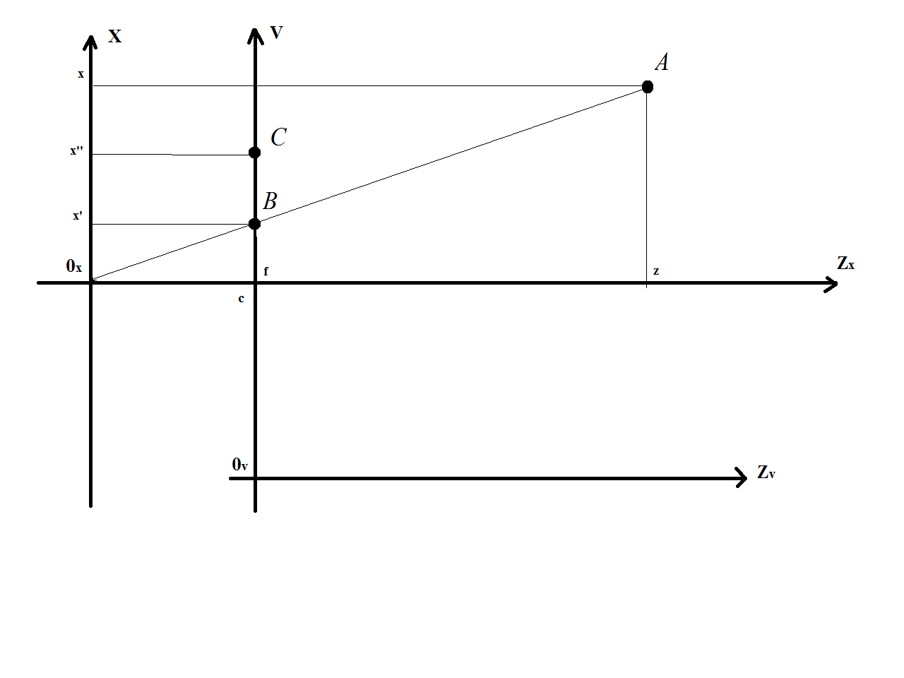
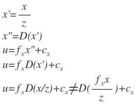
| 2014-02-20 06:58:01 -0600 | edited question | CameraCalibration -> Documentation -> Focal Lengths Hi, everyone. I have one question about FocalLenght in documentation in CameraCalibration. Now we have formula like this:
Am I right? Or I do not understand something? EDIT:
|
| 2014-02-19 02:27:52 -0600 | commented answer | CameraCalibration -> Documentation -> Focal Lengths Second, there is a theoretical justification for undistorting points after perspective division. From an optical point of view the lens warps light rays after they are reflected off surfaces in the scene (so according the objects 3D pose in the camera coordinate system, after perspective division), but before the rays land on the image chip. This is way the undistortion equations are performed before projection on the image plane. Technically speaking projection on the image plane is just an affine transformation, so technically it would be possible to perform undistortion using image coordinates, but this would require reestimating image the distortion factors in image coordinates as most calibration software estimates distortion in ideal coordinates. |
| 2014-02-19 02:16:44 -0600 | commented answer | CameraCalibration -> Documentation -> Focal Lengths First, both u,v and x',y' are in a coordinate system, although different ones. The former, u,v are in image coordinates, whereas x',y' are in so called ideal camera coordinates, that is before decentering and projection on the image plane. |
| 2014-02-18 08:33:46 -0600 | answered a question | Calibrating an uncalibrated camera from another calibrated camera No I do not believe this is directly possible, at least not with a single view configuration and fundamental matrix. The fundamental matrix has 7 degrees of freedom, whereas the general camera projection matrix P = K [R | t] has 10 degrees of freedom (assuming image pixels are not skewed), so that the fundamental matrix alone cannot provide enough constraints. |
| 2014-02-18 08:18:22 -0600 | answered a question | CameraCalibration -> Documentation -> Focal Lengths The answer lies in the magic performed in the two middle rows of the projection equations involving x'' and y''. Assuming you have a camera that perfectly models the pinhole projection model, you could completely skip the x'' and y'' steps and just use the four equations involving x', y', u, and v. But this is not true of most (all?) cameras in practice. The camera's lens introduces distortion that deviates the projection of 3D scene points P = [X, Y, Z] from their ideal image coordinates (as predicted by the pinhole model) p = [u, v] to distorted coordinates p* = [u, v]. This effect varies depending on the quality of camera and the type of lens, typically points are warped away from the principal point proportional to their distance (positive radial distortion). The equations involving x'' and y'' are compensating the lens distortion, which must be done projecting the points onto the image plane. See Szeliski chapter 2.1.6 for more info. EDIT: As to why distortion correction is (almost) always applied before projection on the image plane. First, you are arguing about right and wrong, i.e. your proposed equations are right is right and OpenCV is wrong. This is not a fruitful way to look at the problem. Basically the pinhole camera model defines a set of conditions that any projection of a scene has to obey, the size of an object is inversely proportional to its distance to the camera, directly proportional to the focal length etc, directly related to its pose relative to the camera etc... Distortion correction is just a way of fitting an imperfect physical system fit into this ideal mathematical model, there is no one absolutely correct way it must be applied, as long it makes the imaging process closer to the pinhole camera model. So yes you could perform distortion after projection on the image plane but before decentering, but this will require that your distortion function is estimated using image coordinates and not normalized camera coordinates. The distortion function is a non linear function without an explicit representation that is approximated via Taylor expansion up to 6th degree terms (depending on OpenCV flags), and it is dependent upon the coordinate system in which it was estimated. Because of this non linearity you cannot switch the order in which it is performed:
So if you want to use your projection equations you have to reestimate the distortion function in image coordinates. Now there is a reason why distortion correction is typically performed as the OpenCV equations dictate, that is in normalized camera coordinates. Estimation of the distortion functions is performed during camera calibration where a planar pattern with a set of accurately known points is observed by the camera from many viewing angles and distances. Typically one of the first steps involves estimating the pose of the calibration target relative to the camera for each input image. Knowing the pose of the calibration pattern relative to the camera means you can ... (more) |
| 2014-02-17 11:44:20 -0600 | answered a question | Camera Undistortion The distortion parameters are independent from the camera's extrinsic parameters. In other words the distortion parameters do not change if you move the camera around. The only time the distortion parameters change is if you change the lens settings of your camera. |
| 2014-02-04 03:14:46 -0600 | commented question | Construction of Camera matrix You can construct the camera (projection) matrix using the rotation, translation, focal lengths and principle points. You do not need a 3d - 2d point correspondence in this case. |
| 2014-02-04 03:08:45 -0600 | commented answer | Construction of Camera matrix I would note that assuming a general pinhole camera model (I am unaware of any Zhang camera model), there is no need to separate the extrinsic and intrinsic steps in the projection and you not need to normalize (unless performing distortion removal, which was not asked). In general you can formulate it as p = [K] [R | t] [P 1], where K is the calibration matrix, R = RxRyRz the composition of the eurler angle matrices, and t the translation. |
| 2014-02-04 02:05:12 -0600 | commented answer | calibration transformation matrices This is not an answer to the question. If want an answer for your problem please open a new question and consider formulating it a bit more clearly. |
| 2014-02-04 01:51:22 -0600 | commented question | OpenCV on OSX Mavericks in Xcode CMake really shines when you have: 1) lots of third party dependencies and 2) when your code should compile and run on multiple platforms. If you only ever target OS X I can understand leaving it out, but if your project's scope grows you may want to reconsider using CMake in the future. |
| 2014-02-02 05:42:39 -0600 | commented question | OpenCV on OSX Mavericks in Xcode Why don't you use CMake for your project as well? Then you can just automatically generate a properly configured Xcode project. |
| 2014-01-29 02:14:12 -0600 | received badge | ● Citizen Patrol (source) |
| 2014-01-28 12:30:07 -0600 | commented answer | OpenCV + CUDA + OSX 10.9 While cuda is linked against libstdc++, that doesn't mean it couldn't be used against apps that use libc++, both standard libraries can peacefully coexist in the same app. You would just have to make sure that all the cuda is in a separate library, and that the library does not make use c++ classes that live in std. This is the problem with OpenCV, their CUDA functions take c++ classes from the standard library (string for example), thus preventing the library from safely coexisting libc++ code. |
| 2014-01-28 09:09:48 -0600 | commented answer | From Fundamental Matrix To Rectified Images I updated my answer to reflect that you were not checking for degenerate essential matrix decompositions, and I added a gist in python of how you can perform the decomposition correctly. The OpenCV stereo rectification still isn't great with the images you posted, but it does not exhibit the symptoms you described above. |
| 2014-01-27 04:29:58 -0600 | commented answer | From Fundamental Matrix To Rectified Images Can you maybe post a link to image with your key point matches drawn on, as well as the resulting incorrect stereo rectified image? |
| 2014-01-27 04:24:58 -0600 | commented answer | From Fundamental Matrix To Rectified Images Estimation of the fundamental matrix only depends on the point correspondences. Your choice of feature detector / descriptor determines whether color (RGB) or intensity information is used for estimation point correspondences. SURF does not use color information if I recall correctly. Maybe you could try other detectors / descriptors like FREAK, ORB etc? |
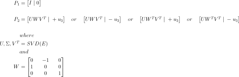
| 2014-01-24 15:24:06 -0600 | answered a question | From Fundamental Matrix To Rectified Images Upon looking into your problem in more detail, the source of your rectification errors has become a bit more obvious. Your processing pipeline up until the decomposition of the essential into rotation and translation is mostly correct (see comments further below). When decomposing the essential matrix into rotation and translation components, there are actually 4 possible configurations, where only one of them is actually valid for a given camera pair. Basically the decomposition is not unique because it allows degenerate configurations where one or both of the cameras are oriented away from the scene they imaged. The solution to this problem is to test if an arbitrary 3D point, derived from a point pair correspondences between both images, is located in front of each camera. In only one of the four configurations will the 3D point be located in front of both cameras. Assuming the first camera is set to the identity the four cases are:
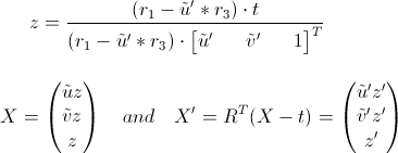
where P1 is the camera matrix for the first camera and P2 for the second. Testing whether any given 3D point, derived from a point correspondence in both images, is in front of both cameras for one of the four possible rotation and translation combinations, is a bit more involved. This is because you initially only have the point's projection in each image but lack the point's depth. Assuming X, X' is a 3d point imaged in the first and second cameras coordinate system respectively, and (ũ,ṽ), (ũ', ṽ') the corresponding projection in normalized image coordinates, in the first and second camera images respectively, we can use a rotation translation pair to estimate the 3D points depth in each camera coordinate system:
where r1 .. r3 are the rows of the rotation matrix R and translation t. Using the formula above for a point correspondence pair you can determine the associated 3D point's position in each camera coordinate system. If z or z' are negative, then you know you have a a degenerate configuration and you have to try one of the other three essential matrix decompositions. I have made a gist of this in python here: https://gist.github.com/jensenb/8668000#file-decompose_essential_matrix-py Besides this You are not performing rectification (undistortion) prior to feature extraction / matching, which can cause some problems down the line, depending upon how strong the lens distortion is in your setup. Estimation of the fundamental matrix depends upon having point correspondences between both images that are undistorted (as near ideal pinhole camera as possible). Lens distortion is nonlinear and depending upon how close the matched features are to the center of projection, you will get more or less correct fundamental matrix estimates, which directly effects the quality of the stereo rectification. So to summarize I recommend performing undistortion immediately after reading in your input images. |
| 2014-01-22 01:28:38 -0600 | commented answer | Building OpenCV in Mac Os X (10.9.1) - video library error Also please use the comment function instead of creating answers to the question. |
| 2014-01-22 01:26:09 -0600 | commented answer | Building OpenCV in Mac Os X (10.9.1) - video library error This is a separate and likely unrelated issue to the one that tin posted in the question. Note that his build log does not mention missing symbols anywhere. You should open a separate question and include a full build log. |
| 2014-01-22 01:25:28 -0600 | commented answer | Building OpenCV in Mac Os X (10.9.1) - video library error Also please use the comment function instead of creating answers to the question |
| 2014-01-22 01:24:45 -0600 | commented answer | Building OpenCV in Mac Os X (10.9.1) - video library error This is a separate and likely unrelated issue to the one that tin posted in the question. Note that his build log does not mention missing symbols anywhere. You should open a separate question and include a full build log. |
| 2014-01-21 15:35:50 -0600 | answered a question | Building OpenCV in Mac Os X (10.9.1) - video library error This is a known issue on Mavericks: http://code.opencv.org/issues/3359. You will have build OpenCV without Quick Time support "-D WITH_QUICKTIME=OFF", which may or may not affect you, depending upon whether you absolutely need hardware acceleration for video playback. The FFMpeg based video play functionality works just fine for me. |