This forum is disabled, please visit https://forum.opencv.org
| 2020-11-05 23:46:47 -0600 | received badge | ● Popular Question (source) |
| 2018-11-06 09:08:23 -0600 | commented answer | canny on RGB color wrong... opencv can handle rgb images directly, I don't know what it does though under the hood |
| 2018-10-15 06:32:07 -0600 | commented question | Compile the dnn module against the system version of opencv @dkurt https://github.com/opencv/opencv/wiki/TensorFlow-Object-Detection-API |
| 2018-09-26 10:30:07 -0600 | commented question | Compile the dnn module against the system version of opencv The troll was already clear with the virtual machine |
| 2018-09-26 09:54:09 -0600 | commented question | Compile the dnn module against the system version of opencv I don't see any great advantage of colab compared to an AWS EC2 instance with a dedicated Tesla K80, am I missing someth |
| 2018-09-26 09:11:52 -0600 | commented question | Compile the dnn module against the system version of opencv And as for my goal, it is to do forward inference in order to segment an image, without having to install tensorflow. Th |
| 2018-09-26 09:10:57 -0600 | commented question | Compile the dnn module against the system version of opencv And as for my goal, it is to do forward inference in order to segment an image, without having to install tensorflow. Th |
| 2018-09-26 09:08:21 -0600 | commented question | Compile the dnn module against the system version of opencv Due to strict controls on the software on the target product as well as of the deployment pipeline, this is not feasible |
| 2018-09-26 08:52:30 -0600 | asked a question | Compile the dnn module against the system version of opencv Compile the dnn module against the system version of opencv I am using Ubuntu Bionic (18.04) which comes with opencv 3.2 |
| 2018-09-05 07:35:07 -0600 | commented answer | Using minAreaRect with contour in Python No they are not a waste of time as the purpose of this website is to publicly document all possible problems users might |
| 2016-10-14 08:37:55 -0600 | commented answer | Camera pose (pitch, roll, yaw) from observing ceiling from two different positions Optimization or Kalman filter worked for me. |
| 2016-10-14 08:36:27 -0600 | commented answer | RANSAC and 2D point clouds @sammy , under some constraints (you know the relation is an affine transform for example), in most real world cases there is only one transform. |
| 2016-09-26 03:50:36 -0600 | asked a question | Optimal shape for PnP on calibration pattern I have a setup where I need extrinsic calibration of an actuator where a camera is mounted. The camera is already calibrated relative to the actuator and now I need to calibrate the whole system relative to some kind of shelf. I need the distance from that shelf and the angle relative to that shelf. I tried using AR markers (AR track alvar) on the shelf but the accuracy is highly dependent on the print quality and even then it is still relatively unstable. When I visualize the marker's detection in Rviz (a ROS software) I see that the markers are not always collinear, where in reality they are just put next to each other on a planar surface. This planar surface is the only free place where I can put markers and it has dimensions of 30x3 cm. I thought about putting a calibration pattern there (the black dots). However, this calibration pattern will not be close to a square shape and will be much thinner and longer. Do you have any suggestions on what I should consider before doing that? Would it still work well with a 3x20 shape? I am targeting accuracy ranges under one millimeter and one degree. The intrinsic calibration of the camera returns a re-projection error under 1 pixel. |
| 2016-09-12 07:26:48 -0600 | commented answer | What does projection matrix provided by the calibration represent? at the end you mean [K' | 0] for rectified image and [K | 0] for raw image right? That is what is written in the ros message comments. |
| 2016-09-12 07:03:35 -0600 | commented answer | What does projection matrix provided by the calibration represent? P is quite confusing here, the answer from @windonground is more correct. To reproject points from camera frame to pixels, you should use different matirces depending on the image you want to project on (raw distorted image or rectified image). |
| 2016-06-30 09:33:51 -0600 | commented answer | How to use MSER in Python old is a relative term, many systems, especially in robotics are still using opencv 2.4, mainly because Ubuntu doesn't integrate opencv3 yet as a package. Your answer is only valid for opencv 3. here is a comparison |
| 2016-06-30 09:32:15 -0600 | received badge | ● Critic (source) |
| 2016-04-04 03:49:14 -0600 | commented answer | DIST_L2 missing in version 2.4.8? (segmentation demo fails) it is not like they just want to do it so to annoy people. In order to get ROS to be installable using sudo apt-get, all the dependencies should also exist as repositories. For Ubuntu 14.04, opencv 3 is not there yet. So this is a Canonical and OpenCV folks problem. |
| 2015-02-11 01:44:03 -0600 | commented question | Error while building OpenCV on Raspberry PI why are you compiling it directly on the board? Wouldn't be faster to do it by cross compiling on your more powerful computer first? |
| 2015-02-10 00:35:12 -0600 | received badge | ● Enthusiast |
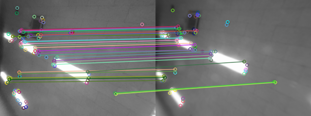
| 2015-02-09 21:43:12 -0600 | asked a question | findFundamentalMat not correctly filtering outliers After detecting keypoints and matching them between two images, I run findFundamentalMat to estimate the Fundamental matrix and also filter the outliers. When I draw the matches using the mask I get from findFundamentalMat, there is sometimes some matches that are not filtered out eventhough they clearly don't fit in the transform. Here is an example of a good filtering (Left image from robot's camre, right image static):
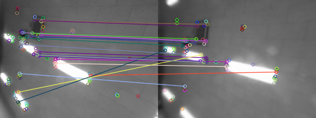
But without moving the robot, the matches change a lot from one picture to the next (due to the flickering in the light?) And often there is one wrong match or two that are left. I suspect those matches to cause the inconsistency in my estimated Fundamental matrix which can look totally different from one image to the next, even without moving the robot.
Here the yellow and blue line clearly don't fit to the model. Could they cause the fundamental matrix to go totally wrong? |
| 2015-01-30 00:58:47 -0600 | commented answer | Only one match per keypoint Thanks ! somehow I oversaw this in the docs |
| 2015-01-30 00:58:33 -0600 | received badge | ● Supporter (source) |
| 2015-01-30 00:58:32 -0600 | received badge | ● Scholar (source) |
| 2015-01-28 20:59:59 -0600 | asked a question | Only one match per keypoint I am trying to use Lowe's criteria to remove bad matches but I realised that I get only one match per keypoint. Why is that? Those are my matcher, detector and descriptor And the function I use to remove bad matches by comparing the distance of the first best and second best matches, but I only have the first best match (for each m in matches there is only one DMatch object and not an array). |
| 2015-01-28 20:06:26 -0600 | received badge | ● Editor (source) |
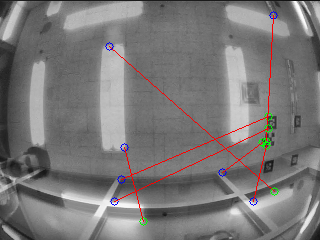
| 2015-01-28 19:55:10 -0600 | asked a question | Fast outliers detection I have a situation where I am trying to recognize a scene my robot already mapped. For that I match keypoints from the current robot's view to all images corresponding to the keyframes of my map. Just from seeing the matching results I can as human tell if it is a good one or a false positive. Like in the images below where I superpose both images. I use brisk descriptors, goodFeaturesToTrack detector and binary matching.
Here the two scenes are totally different but contain similar lamps and I can see that the matching lines are crossing each other so it is a wrong match
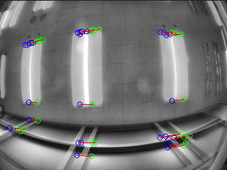
Here however, the matches are nicely aligned and I can tell this is the right scene being matched. Normally even when having the right scene I still have some outliers and the results in the images shown here are after using cv2.detectHomography and masking as much outliers as possible. What I tried until now is to calculate the remaining matches after outliers removal and the image with the maximum number of filtered matches wins. It is however not very stable with many false positives and it is too slow even for offline processing. My questions are: Is there a method to remove outliers without having to estimate the homography? How can I write a fast algorithm to detect if the matches "flow" in one direction or that if they are degenerate. By flow I mean that they either represent a translation or a rotation in plane as my robot as a fixed camera looking at the ceiling and moves on wheels. |
| 2015-01-20 00:58:22 -0600 | asked a question | Camera pose (pitch, roll, yaw) from observing ceiling from two different positions Until now I was using AR Markers for estimating the angles of my camera mounted on a robot. But I believe there is enough information in corners matched between two images of a planar ceiling taken from for example positions (x, y, z) and (x+1, y, z) where there is a known translation between both positions. The coordinate are defined in the world frame in which the ceiling is at z = constant. I am trying to figure out what the equation would be but with no success yet. |
| 2014-11-16 20:48:01 -0600 | asked a question | Detect single mini chessboards I'm in a situation where I need to detect separate mini chessboards (2 black squares 2 white squares). I was searching inside the source code for the function doing this kind of detection but I couldn't find it. Can somebody give me a hint? And I also was wondering if the function findChessboardCorners() just finds these points where two black squares are intersecting or if it also runs some optimization algorithm to force the points to form parallel lines. |