I've noticed that for rectangles with large rotation angles, the "minAreaRect" gives results with better accuracy - when the angle is small, the results have a pixel resolution and when it increases, there is a sub-pixel resolution.
This phenomenon can be seen, for example, when simulating lens distortion effects. When displaying the detected rectangle dimensions as a function of its position in the frame, one can see the following (10 degrees rotation on the left, 0 degrees on the right):
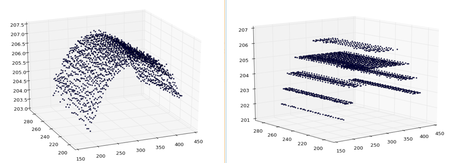
What is the explanation for this? Is there perhaps a quick fix?
Lens distortion simulation code in python:
#
import numpy as np
import cv2
import glob
import pylab
import matplotlib.pyplot as plt
from mpl_toolkits.mplot3d import Axes3D
from scipy.interpolate import griddata
import numpy as np
import re

width = 620
height = 480

map = pylab.zeros((height,width))
x = pylab.zeros((height,width))
y = pylab.zeros((height,width))
for i in range(height):
    for j in range(width):
        xx = i - height/2
        yy = j - width/2
        x[i,j] = i
        y[i,j] = j
        if xx==0 and yy==0:
            map[i,j] = 0
        else:
            map[i,j] = float(xx ** 4 + yy ** 4)

distortion_factor = 0.08
map = distortion_factor * map/map.max() + (1 - distortion_factor)
map32 = map.astype('float32')
map_x = (np.multiply(map32,x-height/2)+height/2)
map_x = map_x.astype('float32')
map_y = (np.multiply(map32,y-width/2)+width/2)
map_y = map_y.astype('float32')

margin = 200
dec = 3

angle = 0.0
for x in range(int((width-margin*2)/dec)):
    for y in range(int((height-margin*2)/dec)):
        rect = ((margin+x*dec, margin+y*dec), (188, 188), float(angle))
        box = cv2.boxPoints(rect)
        box = np.int0(box)
        img = cv2.imread('blank.png', 0)
        img = img[0:height, 0:width]

        cv2.drawContours(img, [box], -1, 0, -1)
        img = cv2.remap(img, map_y, map_x, cv2.INTER_CUBIC)

        file_name = 'distortion/customRect x%f_y%f_o%f.png' % (x*dec+margin,y*dec+margin,angle)
        cv2.imwrite(file_name, img)

x = []
y = []
x_est = []
y_est = []
angle_est = []
width = []
height = []

for rectImg in glob.glob("distortion/*.*"):

    img = cv2.imread(rectImg,0)
    im2, contours, hierarchy = cv2.findContours(img, cv2.RETR_LIST, cv2.CHAIN_APPROX_SIMPLE)

    try:
        cnt = contours[-2]
        cv2.drawContours(img, [cnt], -1, 0, -1)
        rect = cv2.minAreaRect(cnt)

        x_est.append(rect[0][0])
        y_est.append(rect[0][1])
        angle_est.append(rect[2])
        width.append(rect[1][0])
        height.append(rect[1][1])

    except:
        pass


fig = pylab.figure()
ax = Axes3D(fig)
ax.scatter(x_est, y_est, width, marker='.', depthshade=False)

pylab.show(block=True)
