solvePNP inconsistency when rotating markers on a plane
I'm implementing a 3d laser scanner based on a rotating table with aruco markers on it for camera pose estimation.
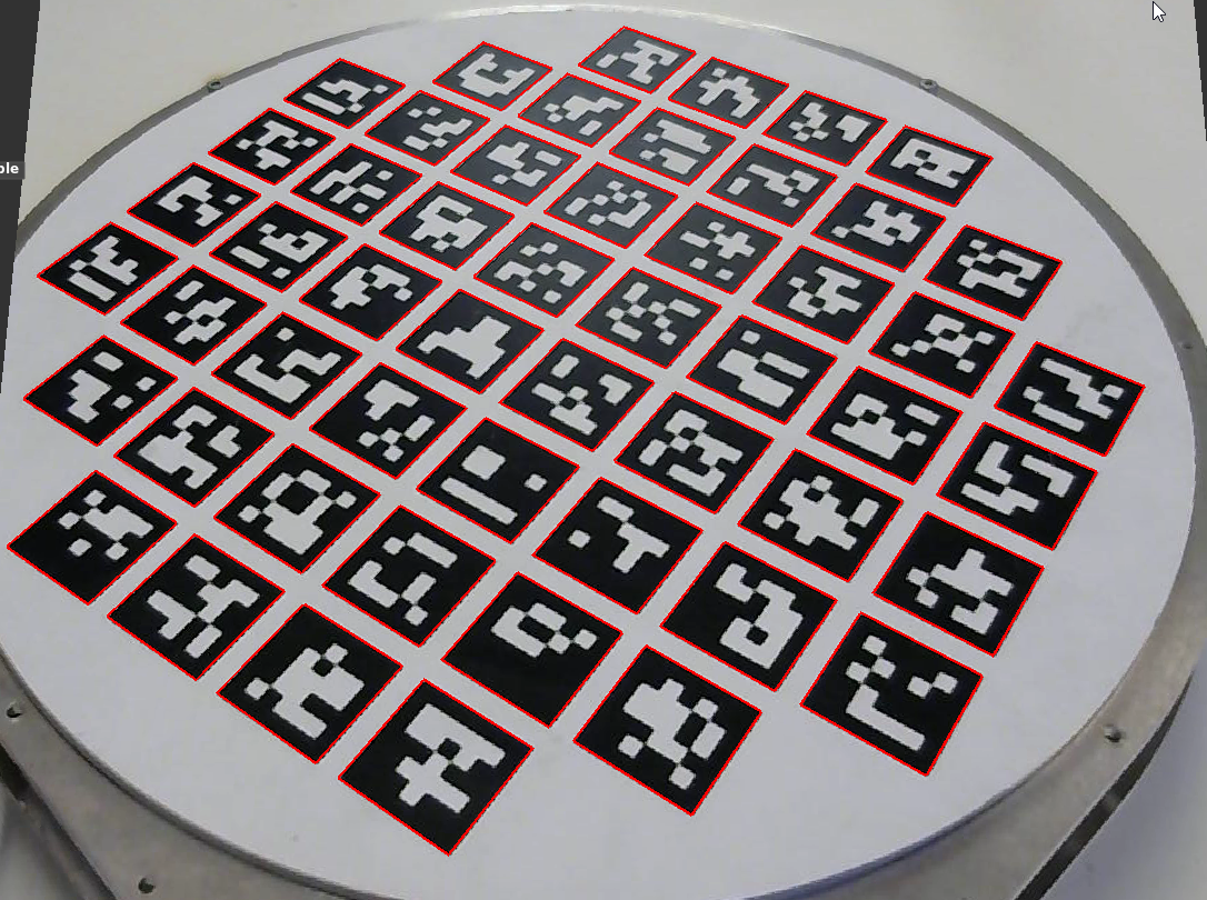
Here is a sample captured camera frame, with the aruco markers detected:
The basic pose estimation flow (for one frame) can be summarized as follows:
camera_matrix, distortion_coefficients = readCalibrationParameters()
board_configuration = readBoardConfiguration()
frame = captureCameraFrame()

found_marker_corners = aruco::detectMarkers(frame, board_configuration)

rvec, tvec = cv::solvePNP(found_marker_corners, board_configuration,
                                      camera_matrix, distortion_coefficients)

R = cv::Rodrigues(rvec)
R = R.t();

camera_position = (-R * tvec);
As the scanner's turntable is flat, the computed camera's Z position (height) should be consistent when rotating the turntable around.
However, this is not the case.
There is a direct relationship between the perceived angle of marker's rotation and the computed camera's Z position, with extremes when the marker is seen straight on and when it's rotated by 45 degrees.
The following charts illustrate this relationship.
EDIT: The charts have been replaced with ones based on synthetic images, so as to make sure the problem is not related to some physical-world phenomena and constrain the problem domain to purely algorithmic. The previous images may be still viewed here.
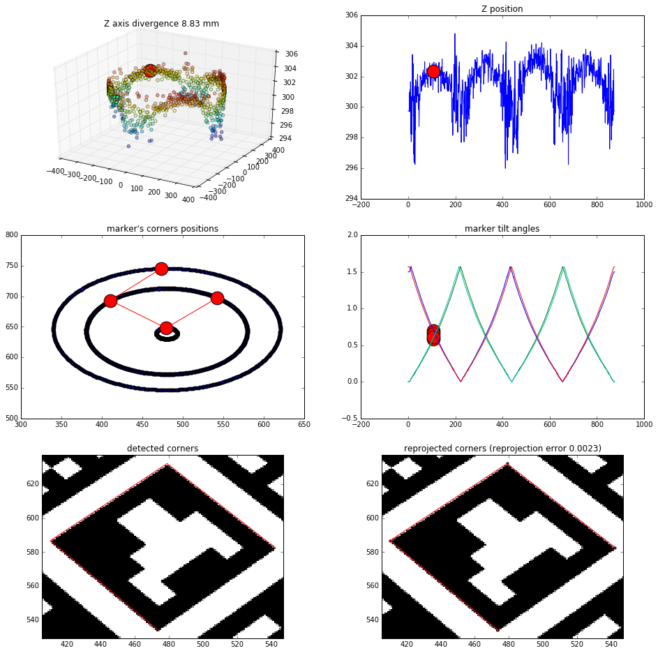
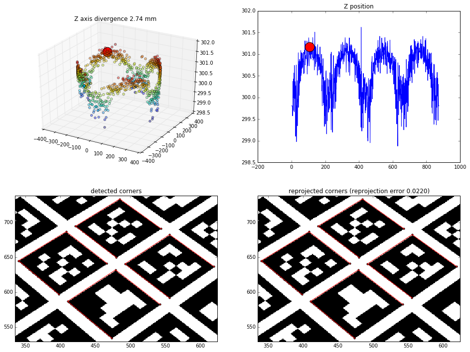
Single marker results
Effects of finding the camera position based on just one marker (4 points to solvePNP)
Straight view:
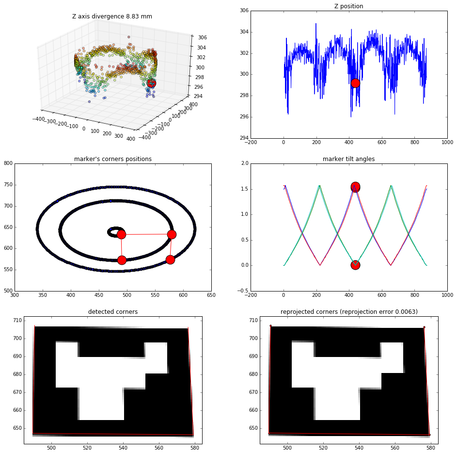
View from 45 degrees rotation:
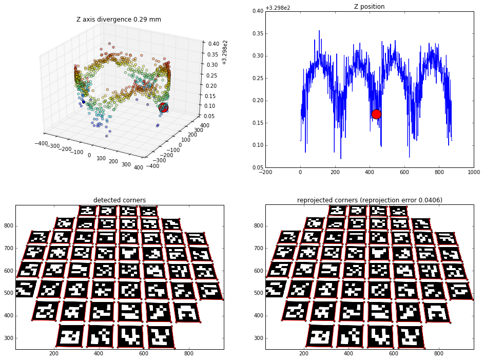
4 middle markers results
Effects of finding the camera position based on the 4 middle markers (16 points to solvePNP)
Straight view:
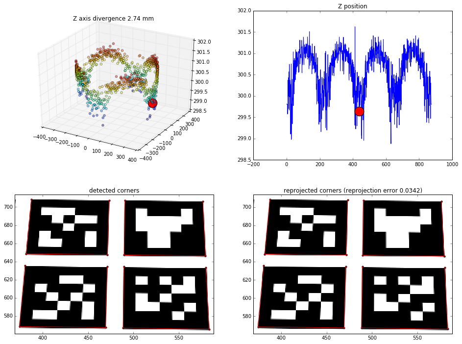
View from 45 degrees rotation:
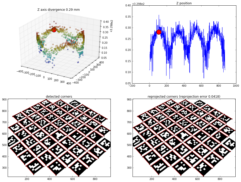
All markers results
Effects of finding the camera position based on all the markers (~200 points to solvePNP)
Straight view:
View from 45 degrees rotation:
Already checked
Some of the things I tried which had no effect on the problem (the relationship was still there):
- using low-resolution camera frames (320x240)
- detecting 4 extra-large markers instead of 52 small ones
- using a different camera
- using different camera calibration / using zero distortion
- changing corner detection parameters
- using the two other solvePNP methods, CV_EPNP and CV_P3P (the relationship was still there, but the precision was much worse)
Are the results a limitation of solvePNP, or am I doing something wrong?
Edit:
- updated the pseudocode to clarify the used methods, according to suggestions
- added separate charts for 1-marker, 4-marker and all-marker position calculation
- added reprojection error for the detected points
Edit 2:
It turned out that the printed markers were not exactly square (1mm difference across the entire table), which made some results worse than they should be. After correcting for that, the main problem still remains, however.
I have replaced the images with ones generated synthetically so as to ensure that the problem is algorithm-related (and not related to, say camera calibration or physical dimensions mismatch).

First of all, this a great detailed question! Just some questions or advices:
invert, just in case of.Thanks for the suggestions, Eduardo!
I've updated the original question with some of them (and will continue to should I reach further conclusions).
As for the distance, the camera is located about 35cm from the middle of the roundtable. The pattern of found positions is regular enough for me to believe it to have a reason that can be understood, and through it, compensated for.
The reprojection error for the camera calibration (standard opencv with chessboard pattern) used for the position estimation is 0.44.
I never used Aruco but it seems that corner refinement is disabled by default.
You could try to enable it if it is not already done and see if the precision increase or not.
Your image is undistorted, right? Are you accidentally passing in non-zero distortion parameters?
@Eduardo I had corner refinement enabled for my experiments. Disabling it retains the same tendency, only makes the computed camera positions more spaced out.
Do you think corner detection could be biased based on the angle of the corner?
Thank you for the updates and for the interesting results/works.
If you want to completely eliminate the image processing part, maybe you could try to use directly for the 2D image coordinates of the corners the back projection of the 3D coordinates?
Just an idea, as you use now synthetic data, maybe you could try to plot the real distance to the world frame and see if the shapes correspond? Also plot directly the Z error to see if there is a correlation between distance to world frame and Z error?
Or maybe the effect is not due to the distance but rather the rotation of one axis?
Unfortunately, I am not enough qualified but I would like to know if this effect is due intrinsically to the method (how the method solves the PnP problem) or numerical imprecision.