implementation calibration (zhang) homography problem [closed]
Hey guys,
i've started to implement zhangs algorithm for a camera-calibration(2D-Rig). Now i've got a fundamental issue at the beginning. I think i'm getting a wrong homography.This can be seen by looking at the image. The red dots are the detected corners by findChessboardCorners() and the blue circles are a transformation (homography) by the 3D-Points to the image-points.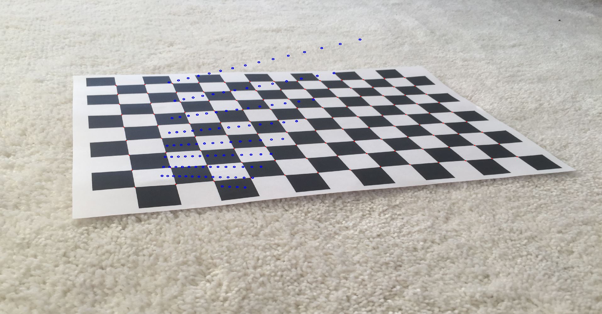
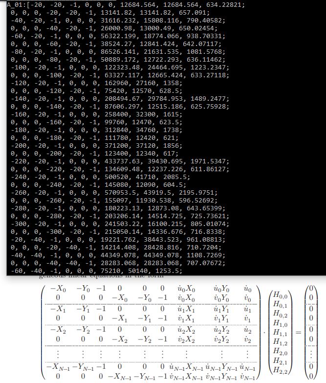
I dont know what the problem could be, because the Design-matrix(the matrix to solve homogeneous equation system with svd and so get the homography vec) seems to be right (but i also attach a screenshot of the matrix). The width and height of a square a 20mm. Image size 3200x2400.! Design Matrix:
Could anybody pls tell me what the issue may be? I dont have any clue, but i think the computations of the svd should be correct because ive checked it with other online-svd-calulators.
Thanks
cv::Mat calib_img_copy = calibImg->clone();
    //detected corners is output of findChessBoardCorners()
cv::Mat homogenous_image(3, m_detectedCorners.rows,CV_32FC1);
cv::Mat homogenous_world(3, m_detectedCorners.rows, CV_32FC1);

char counter = 0;   char image_row = 1; char image_col = 1;

    //Writes matrices (2D and 3D-Coordinates without z) in desired form
for (int i = 0; i < m_detectedCorners.rows; i++)
{
    cv::Point2f k(m_detectedCorners.at<float>(i,0), m_detectedCorners.at<float>(i, 1));
    cv::circle(calib_img_copy, k, 2, cvScalar(0, 0, 255), 2, 1);

    //put the detected corners in homogeneous form into vector
    homogenous_image.at<float>(0, i) = k.x;
    homogenous_image.at<float>(1, i) = k.y;
    homogenous_image.at<float>(2, i) = 1.0f;

    homogenous_world.at<float>(0, i) = 20*image_col;
    homogenous_world.at<float>(1, i) = 20*image_row;
    homogenous_world.at<float>(2, i) = 1.0f;

    image_col++;

    if (counter == 14)
    {
        image_row++;
        image_col = 1;
        counter = 0;
    }
    counter++;
}

m_homogenous_image = homogenous_image;
m_homogenous_world = homogenous_world;

    //Gets design Matrix, with it the homogeneous equation system can be solved
cv::Mat A_01 = getDesignMatrix_camera(m_homogenous_image, m_homogenous_world);

cv::Mat H_01 = solve_dlt(A_01);   //desired homography
cv::Mat converted = H*m_homogenous_world;    //calculate the "projected 3D Points"

   //draw homogeneous coordinates / convert them to inhomogen
for (int i = 0; i < m_homogenous_world.cols; i++)
{
    float kl = converted.at<float>(2, i);
    cv::Point2d h(converted.at<float>(0, i) / kl, converted.at<float>(1, i) / kl);

    cv::circle(calib_img_copy, h, 5, cvScalar(255, 0, 0), 3);
}
cv::namedWindow("Detected Points", CV_WINDOW_KEEPRATIO);
cv::imshow("Detected Points", calib_img_copy);
cv::waitKey();
cv::Mat cComputerVision::getDesignMatrix_camera(cv::Mat& points2D, cv::Mat& points3D) {
  //should write the matrix as shown in the upper picture
cv::Mat base = points2D;
cv::Mat attach = points3D;
cv::Mat design = cv::Mat::zeros(base.cols * 2, 9, CV_32FC1);

int indx;

for (int i = 0; i < base.cols; ++i)
{
    indx = i * 2;

    for (int j = 0; j < 3; ++j)
    {
        design.at<float>(indx + 1, j + 3) = design.at<float>(indx, j) = -base.at<float>(2, i) * attach.at<float>(j, i);
        design.at<float>(indx, 6 + j) = base.at<float>(0, i) * attach.at<float>(j, i);
        design.at<float>(indx + 1, 6 + j) = base.at<float>(1, i) * attach.at<float>(j, i);
    }
}
return design;
}
cv::Mat cComputerVision::solve_dlt(cv::Mat& A) {
cv::SVD svd(A, cv::SVD::FULL_UV);

cv::Mat H ...
Post your code.
Is that printed in a rigid paper? Because it doesn't look so! To start in the best way, I suggest you to print the chessboard in high quality and rigid surface, or at least, attach this paper to something rigid! This will doesn't fix your problem, but is a good start :)
I haven't had a chance to look at the code yet, but I did examine the image more closely. One thing that I noticed is that the grid in the calibration target (red circles) is 9x13 = 117 points, but the transformed grid (blue circles) is 8x14 with the top row having 15 dots, and a small bottom row having 4 dots. This gives the same total (117 points) but the structure is different. I would start by figuring out what this issue is and fixing it first. It's possible it is related to (or will shine the light on) your underlying problem.
**, i should have had a closer look to that design matrix..you are completly right, there was a mistake with the dots (mistake in writing my 3D-Point array in the for-loop)..thank you :), stupid mistake
unfortunately closed the question with the wrong reason -.-