Ask Your Question
0

Charuco calibration

asked 2019-03-14 06:01:34 -0600

LBerger gravatar image

updated 2019-03-14 06:52:14 -0600

In calibrateCameraCharuco only interpolated chessboard corners are used, aruco corners are not used Why ?

if you add aruco corner to calibration rms is really bad

@Eduardo

import numpy as np
import cv2 as cv

def permutation_taille(pts_aruco):
    for ir in range(len(pts_aruco)):
        d1, d2, d3 = pts_aruco[ir].shape
        pts_aruco[ir] = pts_aruco[ir].reshape((d2, d1, d3))
    return pts_aruco

detectorParams = cv.aruco.DetectorParameters_create()
detectorParams.cornerRefinementMethod = cv.aruco.CORNER_REFINE_SUBPIX
detectorParams.cornerRefinementMinAccuracy = 0.01


NBLIGNE = 8
NBCOLONNE = 5
DICO = 14

dico = cv.aruco.Dictionary_get(DICO)
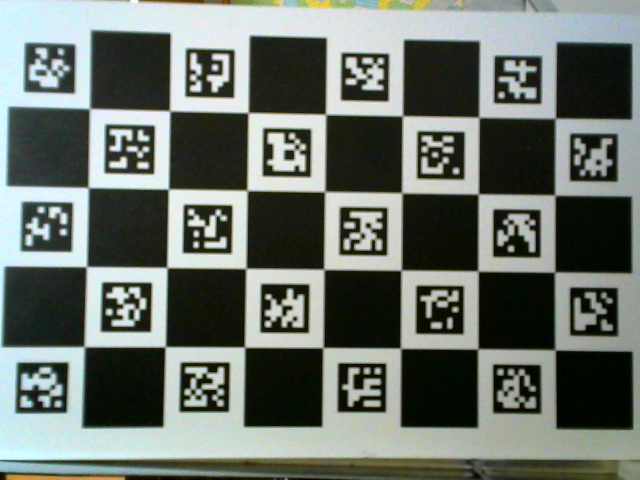
board= cv.aruco.CharucoBoard_create(NBLIGNE, NBCOLONNE,  0.03455, 0.02164, dico)
img = board.draw((1000,1000), 50, 50)
img = cv.imread("imgL.png",cv.IMREAD_GRAYSCALE)
cv.imshow('ChaRuCo', img)
cv.waitKey()
pts_objets = []
pts_camera = []
frame = img.copy()
frame = cv.cvtColor(frame, cv.COLOR_GRAY2BGR)

pts_aruco, ids, refus = cv.aruco.detectMarkers(image=img, dictionary=dico,
                                               parameters=detectorParams)
pts_aruco, ids, refus, recover = cv.aruco.refineDetectedMarkers(
    img, board,
    pts_aruco, ids,
    rejectedCorners=refus)
if recover is not None:
    pts_aruco = permutation_taille(pts_aruco)

extract_aruco =  True
extract_coin = False

if ids is not None:
    retval, coin_charuco, ids_charuco = cv.aruco.interpolateCornersCharuco(
        pts_aruco, ids, img, board)
    if retval == 0:
        print("pb")
        exit()
    rep_error, cam, dist, rvec, tvec = cv.aruco.calibrateCameraCharuco(
        [coin_charuco], [ids_charuco], board, img.shape[0:2],
        None, None, None, None, 0)
    print("RMS = ", rep_error)
    print ("Mat ", cam)
    print ("Dist ", dist,)
    print ("Pose", rvec, tvec)
    cv.aruco.drawDetectedCornersCharuco(
        frame, coin_charuco, ids_charuco)
    cv.aruco.drawDetectedMarkers(frame, pts_aruco, ids)
    pts_reel = None
    echiquier = None
    if extract_aruco:
        for ir in range(len(pts_aruco)):
            if echiquier is None:
                echiquier = pts_aruco[ir][0]
                pts_reel = board.objPoints[ids[ir, 0]]
            elif board.ids[ids[ir, 0]]==ids[ir, 0]:
                echiquier = np.vstack((echiquier, pts_aruco[ir][0]))
                pts_reel = np.vstack((pts_reel, board.objPoints[ids[ir, 0]]))
    if extract_coin: 
       for ir in range(0,ids_charuco.shape[0],3):
            index = ids_charuco[ir][0]
            if echiquier is None:
                echiquier = coin_charuco[ir][0]
                pts_reel = board.chessboardCorners[index]
            else:
                echiquier = np.vstack((echiquier, coin_charuco[ir][0]))
                pts_reel = np.vstack((pts_reel, board.chessboardCorners[index]))
    pts_reel = pts_reel.reshape((pts_reel.shape[0], 1, 3))
    pts_objets.append(pts_reel)
    pts_camera.append(echiquier)
else:
    print("pb")
    exit()


rms, mat_intrin, mat_dist, rvecs, tvecs = \
cv.calibrateCamera(pts_objets, pts_camera, img.shape,
                   None, None, None, None)
print ("rms ", rms)
print ("Mat ", mat_intrin)
print ("dist ", mat_dist)
print ("Pose", rvecs, tvecs)
cv.imshow("frame",frame)
cv.waitKey()

imgl.png

edit retag flag offensive close merge delete

2 answers

Sort by » oldest newest most voted
1

answered 2019-03-16 08:07:56 -0600

Eduardo gravatar image

If I have understood correctly, camera intrinsic parameters and pose estimated with 7x4 chessboard corners give a lower reprojection error than using 7x4 + 4x5x4 points?

If you have correctly updated the 3D objects points to take into account the new 4 Aruco corners, my impression would be that more points would theoretically be better in the ideal case.

Since you have observed the inverse, I agree with @swebb_denver The discrepancy comes most likely from the accuracy of the detected 2D corners. Could be that in one case cornerSubPix is used for Aruco but maybe line intersection is used for chessboard? Or maybe the refinement algorithm works better with corners from intersection compared to corners from a square shape? By the way, it looks like the chessboard squares overlap a little. Maybe the figure or the script generator have to be fixed (see this PR)?

To validate or not this hypothesis, I would generate the camera intrinsic parameters and some realistic camera poses. This way, you can use simulated data and try to see the influence of a small noise in the 2D corner locations with the estimated intrinsics and camera pose. Then, multiple experiments could be done:

  1. accuracy when using only chessboard corners with some noise
  2. accuracy when using chessboard corners + Aruco corners with the same noise applied
  3. accuracy when using chessboard corners + Aruco corners with a bigger noise for the Aruco corners

I would expect:

  • RMS_2 < RMS_3
  • RMS_1 < RMS_3?
  • and normally RMS_2 <= RMS_1

If RMS_2 > RMS_1, in my opinion that would mean that the geometric configuration of the 3D object points influences on the accuracy of the estimation. And, or the repartition of the 2D corners in the whole image.

This is indeed the case but here we should have more or less the same configuration, a regular grid with a rectangular shape, for both cases.

There is a paper on this topic, /cc @racuna :

Insights into the robustness of control point configurations for homography and planar pose estimation, Raul Acuna, Volker Willert

The abstract:

In this paper, we investigate the influence of the spatial configuration of a number of n≥4 control points on the accuracy and robustness of space resection methods, e.g. used by a fiducial marker for pose estimation. We find robust configurations of control points by minimizing the first order perturbed solution of the DLT algorithm which is equivalent to minimizing the condition number of the data matrix. An empirical statistical evaluation is presented verifying that these optimized control point configurations not only increase the performance of the DLT homography estimation but also improve the performance of planar pose estimation methods like IPPE and EPnP, including the iterative minimization of the reprojection error which is the most accurate algorithm. We provide the characteristics of stable control point configurations for real-world noisy camera data that are practically independent on the camera pose and form certain symmetric patterns dependent on the number of points. Finally, we present a comparison of optimized configuration ...

(more)
edit flag offensive delete link more

Comments

Using synthetic data with noise is a good idea. For this case I would add noise to synthetic input images (not image locations) to see the effects of image noise on the image processing for finding Aruco corners vs chessboard corners.

I would also caution against comparing the RMS values of the calibration results directly. Since there are more points in case 2 than in case 1, case 2 may have higher re-projection error even if it is a more accurate calibration. (Consider fitting a line to 2 points vs 50 points, the 2 point line will have zero error, but may not model the rest of the data points well at all).

I would compute re-projection error for a subset of points (not used as input to either calibration) for each method and compare those results.

swebb_denver gravatar imageswebb_denver ( 2019-03-16 09:39:44 -0600 )edit

We can also directly compare the estimated with the true camera intrinsic parameters and the true camera poses.

Eduardo gravatar imageEduardo ( 2019-03-17 07:52:25 -0600 )edit

@Eduardo thanks for your answer. I will use synthetic data to understand the problem

LBerger gravatar imageLBerger ( 2019-03-17 08:20:40 -0600 )edit

How do you compare the intrinsics and extrinsics of the calibrated vs synthetic camera models? It is just by looking at the elements, or is there some function that computes some sort of error based on the models? I haven't been able to come up with a good way to directly compare intrinsics / extrinsics, and I always end up projecting points through both models and computing error in image space. (In some cases I back-project to 3D coordinates (based on the ideal z-depth) and compute error in world space).

swebb_denver gravatar imageswebb_denver ( 2019-03-17 21:33:06 -0600 )edit

For the intrinsics, I would directly compare the elements. For the translation, you can compute the L2 distance error.

For the rotation, you have to compute the rotation difference R_diff = Rest^t x R_true, convert to Rodrigues formalism and look at the angle part (Distance between rotations).

Eduardo gravatar imageEduardo ( 2019-03-18 16:15:04 -0600 )edit

@LBerger Have you had a chance to test with synthetic data? I'd be interested to know the results if you have any.

swebb_denver gravatar imageswebb_denver ( 2019-03-21 13:06:37 -0600 )edit

Yes but sorry not this month

LBerger gravatar imageLBerger ( 2019-03-22 05:42:09 -0600 )edit
1

answered 2019-03-14 12:25:31 -0600

swebb_denver gravatar image

updated 2019-03-15 09:32:28 -0600

The aruco corners aren't nearly as accurate as the chessboard corners, particularly in OpenCV 3.3.1. The chessboard corners are localized more accurately with the cv::cornerSubpix. If you want more points, use a different chessboard grid or more pictures.

[edit: I didn't intend to leave an "answer", but rather a "comment" - I will add some more detail]

The reason only the chessboard corners are used is because they provide more accurate image locations than the Aruco corners. I typically see error reduced by 50% when using the chessboard corners compared to the Aruco corners. (Say, 0.6 pixel re-projection error with the Aruco, and 0.3 pixel re-projection error with the chessboard corners) In my experience there are two primary issues with using the Aruco marker corners as calibration points:

  1. The functions that locate the Aruco markers, particularly in older versions of OpenCV, generated poor corner estimates in many cases. In many cases trying to refine the corner locations with cornerSubpix() was difficult because the initial estimates could be very bad, making it possible to find a corner feature internal to the Aruco marker. Corner accuracy is much better in more recent versions of the Aruco functions, but is still less accurate than chessboard style corners.

  2. cornerSubpix, which is used to generate much more accurate corner locations (as compared to goodFeaturesToTrack, for example) works best on chessboard style corners. CornerSubpix works by analyzing the image (intensity) gradient in a neighborhood of pixels. With a single corner there is not as much supporting gradient information, and probably more importantly the single corner can result in bias from focus or other image formation factors. The double corner of a chessboard corner feature tends to balance out the bias, giving a more accurate corner estimate.

A primary benefit of using a Charuco board vs a standard chessboard is that you don't have to see the full calibration target in your image. This helps in getting calibration points into the corners of the calibration images, which is important for getting accurate distortion parameters, particularly on high distortion lenses. The aruco markers aren't there to generate more data points, rather to provide correspondence points that are accurate enough to predict the (approximate) locations of the chessboard corners. These approximate locations are then refined with cornerSubpix to give very accurate image locations for the calibration target (world) points.

edit flag offensive delete link more

Comments

I'm not sure that's a good explanation

LBerger gravatar imageLBerger ( 2019-03-15 02:45:01 -0600 )edit

Question Tools

1 follower

Stats

Asked: 2019-03-14 06:01:34 -0600

Seen: 2,687 times

Last updated: Mar 16 '19